|
|
ENCYCLOPEDIA OF RADIO ELECTRONICS AND ELECTRICAL ENGINEERING Audio frequency amplifiers EKR1436UN1 and KR1064UN2. Reference data
Encyclopedia of radio electronics and electrical engineering / Reference materials Microcircuits EKR1436UN1 and KR1064UN2 are analogues of the MC34119 microcircuit from Motorola. EKR1436UN1 devices are produced by Integral software (Minsk) in package 2101.8-A in the so-called export version with an inch lead pitch of 2,54 mm (as indicated by the letter E in its name). Microcircuits KR1064UN2 are manufactured by Svetlana JSC (St. Petersburg) in package 2101.8-1 with a metric lead pitch of 2,5 mm (Fig. 1, a). Weight of the device - no more than 1 g.
The Integral software also produces a version of the EKR1436UN1 chip in a miniature plastic package 4309.8-1 (Fig. 1b); the mass of this device is not more than 0,2 g. The MC34119 was designed for use as a 3H signal amplifier in hands-free telephones - often called speakerphones or Hands Free (abbreviated HF) - free hands. Fully meeting the very stringent requirements for working in telephone sets, this microcircuit turned out to be promising for use in amateur designs, primarily in self-powered devices. In many respects, it surpasses the 3H microcircuit amplifiers of the KR174UN23, KF174UN23 and KF174UN2301 series, which are actually specialized for sound amplification in stereo and monophonic players. Among the main advantages of the EKR1436UN1 and KR1064UN2 microcircuits are wide supply voltage limits (2 ... 16 V), the presence of anti-phase outputs, which allows you to almost double the output voltage range (compared to single op-amps) and connect the dynamic head directly to the outputs (without decoupling capacitor). In addition, they are characterized by low current consumption in the absence of an input signal and a small number of attachments. On fig. 2 shows a block diagram of the 3Ch EKR1436UN1 amplifier itself, together with a typical circuit for its inclusion. The amplifier contains the main inverting op-amp 1-DA1 and an additional inverting op-amp 1 - DA2 connected to its output, having a transfer coefficient close to 1.
The device has the ability to switch to low power mode. To do this, a voltage conditionally corresponding to a high level is applied to the blocking input, and the amplifier outputs (pins 5 and 8) go into a high-impedance state, and the current consumption decreases sharply. As soon as the high level at the blocking input changes to low, the amplifier returns to the gain mode. These two modes are illustrated by the graph shown in Fig. 3. Curves taken with no input signal and no load.
The resistance of the blocking input relative to the common wire is approximately 90 kΩ. If the blocking mode is not used, you can leave pin 1 free, but it is better to connect it to a common wire. Capacitors C2 and C3 are used to suppress ripple at the non-inverting input of operational amplifiers 1-DA1 and 1-DA2; C2 - suppresses the high frequency component to a greater extent, and C3 - low frequency. When powering the 3H amplifier from a voltage stabilizer, the capacitance of the capacitor C3 can be reduced or completely abandoned. The transfer coefficient Kp of the amplifier depends on the ratio of the resistance values of the resistors R1 and R2 that form the OS circuit: Kp = 2R2/R1. The factor 2 in this formula is due to the presence of op-amp 1-DA2. Pin 6 of the microcircuit is connected to the positive power wire, and pin 7 is connected to a common wire. Main technical characteristics of UZCH
Performance Limits
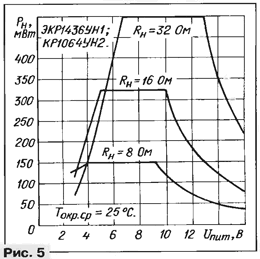
With the diagram shown in Fig. 2 ratings of the OS circuit elements in the frequency range up to 5 kHz gain of at least 46 dB (Kp - 200). By changing the parameters of the OS circuit, it is possible, as for conventional op-amps, to change the transmission coefficient and bandwidth. The power dissipated by the microcircuit is determined by the formula: Ppac \u3d Upit lpot + Upit ln.d. - Rn · In.d, where lpot is determined according to the graph shown in fig. 140; ln.d. - effective value of the load current; Rn - load resistance. The maximum allowable power dissipated by the microcircuit is expressed by the ratio Prac max = = (100 ° C - Tamb.cp) / RT.K_c, where RTk.c is the thermal resistance of the case-environment. For a plastic rectangular case Rt.kc=180 °C/W, the case of a device designed for surface mounting has Rt.kc = XNUMX °C/W. On fig. 4, a - c shows the dependences of the power dissipated by the microcircuit on the useful power allocated to the load, at three values of the load resistance, and in fig. 5 - dependence of the maximum allowable load power on the supply voltage.
The dependences of the harmonic coefficient Kg- on the output power for various values of the supply voltage, load resistance, input signal frequency and gain are shown in fig. 6, a - c. Rice. 6a corresponds to a frequency of 1 kHz and a gain of 34 dB, fig. 6,6 - 3 kHz, 34 dB, fig. 6, in - 1 and 3 kHz, 12 dB.
On fig. 8 shows the frequency characteristics of the amplifier for various parameters of the feedback circuit.
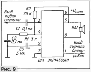
As already mentioned, when a high level voltage is applied to the blocking input, the amplifier goes into micropower mode, in which its output impedance increases sharply. With a low-resistance load (for example, a direct radiation dynamic head) in this mode, the microcircuit is practically turned off, the output signal does not pass. If the load has a high impedance (the input of another amplifier, suppose), the difference in the signal path may not be noticeable. This circumstance must be borne in mind in cases where it is intended to use the blocking mode to control the signal flow. On fig. 9 shows another option for switching on a 3H microcircuit amplifier, which provides a higher input impedance - Rin = 125 kOhm. With the ratings of the elements indicated in the diagram, the suppression of the supply voltage ripple reaches -50 dB.
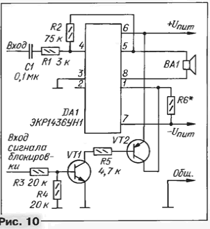
Sometimes it is necessary to apply output signals from several sources to the input of a 3H amplifier, provided that the best mutual isolation of the sources is obtained and the influence of the input circuits on the gain of the amplifier is excluded. In this case, it is convenient to use the scheme shown in Fig. 2. The output of each signal source is connected to the input of the EKR1436UN1 amplifier through its serial circuit of a capacitor and a resistor (only one such circuit is shown in Fig. 2). By changing the resistance of the resistor, it is possible to obtain the required signal transfer coefficient from the corresponding source to the amplifier. Thus, the same volume level is provided at different output levels of the source signals. On fig. Figure 10 shows the option of powering the described microcircuits from a bipolar source with a voltage of 2x (1 ... 8) V. If the shoulders of the bipolar source are asymmetrical in voltage, pin 3 of the microcircuit must be connected to a common wire through a capacitor (see the main typical circuit of Fig. 2).
The presented circuits do not exhaust the possible options for constructing amplifiers, since the described microcircuits have great "flexibility", which allows creating optimal operating conditions for specific designs. Literature
Author: D.Turchinsky
Machine for thinning flowers in gardens
02.05.2024 Advanced Infrared Microscope
02.05.2024 Air trap for insects
01.05.2024
▪ Rotating neutron stars to test and calibrate atomic clocks ▪ Breakthrough in limb regeneration ▪ Lexus RZ 450e electric crossover ▪ Cats understand their owners
▪ section of the site Alternative energy sources. Article selection ▪ article Massacre of the Innocents. Popular expression ▪ Why did Princess Medea of Colchis fall in love with Jason at first sight? Detailed answer ▪ article Two-tone call on microcircuits. Encyclopedia of radio electronics and electrical engineering ▪ Article Match and invisible thread. Focus Secret
Home page | Library | Articles | Website map | Site Reviews www.diagram.com.ua |


 Arabic
 Bengali
 Chinese
 English
 French
 German
 Hebrew
 Hindi
Hindi Italian
 Japanese
 Korean
 Malay
Malay Polish
 Portuguese
 Spanish
 Turkish
 Ukrainian
 Vietnamese


 See other articles Section
  Leave your comment on this article: