|
|


 Arabic
 Bengali
 Chinese
 English
 French
 German
 Hebrew
 Hindi
Hindi Italian
 Japanese
 Korean
 Malay
Malay Polish
 Portuguese
 Spanish
 Turkish
 Ukrainian
 Vietnamese
|
ENCYCLOPEDIA OF RADIO ELECTRONICS AND ELECTRICAL ENGINEERING Optical communication cables of foreign production. Reference data
Encyclopedia of radio electronics and electrical engineering / Reference materials Domestic optical cables were considered in "Radio" No. 10 for 1997. This article is devoted to cables of foreign production, which are widely used on Russian communication lines. As in the previous article, here we use data from the book by I. S. Goldfarb "Development of optical cable technology" (TsNTI "Informsvyae", 1996), as well as prospectuses of various companies for 1997. Now in the world there are dozens of companies engaged in the production of optical cables (OC) for various purposes. Here we consider cables used in local, zonal and backbone FOCL systems. The most widely used are optical cables of the layered type with a single-layer layer. All of them, like domestic ones, are characterized by the same parameters: the attenuation coefficient a (dB/km) for the corresponding transparency window, the number of fibers in the OK, the type of fibers - single-mode or multimode, specific mass (kg/km). allowable tensile force in newtons (N). transverse compression, minimum allowable bending radius (mm), building length, operating temperature range. Currently, 90% of the OCs produced in the world consist of single-mode optical fibers (FO). This is due to that. that modern single-mode optical fibers are cheaper than multi-mode optical fibers and, in addition, optical fibers with single-mode fibers have lower linear attenuation and greater bandwidth. The latter is especially relevant with rapidly growing speeds and volumes of information transfer. All cables of the stranded type with a single-layer lay are characterized by the presence of a core and protective coatings. Inside each polymer tube is one (or more) optical fiber. The tube together with the fiber(s) forms a module. Different materials are used for the core and the central rod, for example. in some designs they may contain metal elements, in others they can do without them. In table. 1 shows the main parameters of OK with a single layer and one fiber in the module.
An optical cable from the General Cable Company contains eight modules, each of which contains one free-lying fiber. The cross section of this cable is shown in Fig.1.
The central polymeric core is fastened with polyester tapes. The modules are bonded and protected by a polyethylene sheath with kevlar threads, over which is wound a layer of reinforcing fibers, which, in turn, is covered with an outer sheath, also with kevlar threads. The cables of this company operate in the second and third transparency windows with attenuation of 0.35..D5 dB/km and 0.2..DE dB/km, respectively. their dispersions are 3,5 ps/nm.km and 2,5 ps/nm.km, respectively. The table shows that the OK of other firms are close to those described above. The main difference lies in the materials used for the reinforcing and protective elements. In optical cables from the Finnish company Nokia (design Fzoniu), the central reinforcing element consists of strong fibers sheathed in low-density polyethylene. The modules are also covered with a layer of high tensile strength synthetic fibers impregnated with a special compound. The outer protective sheath is made of polyethylene. The outer diameter of the cable is 12 mm The optical cable of the same Finnish design company Ffzohbmu has six optical modules and two fillers. At the same time, an aluminum-ethylene tape is used as a moisture-proof barrier. Nokia also produces OK designs Fzohbmpmu. in which an armor layer of galvanized round steel wires is used. The outer sheath of the cable is made of polyethylene. The diameter of the cable is 17,5 mm, its specific gravity is 470 kg / km. This cable is designed for laying directly in the ground. The optical cables of the German company SEL do not have metal reinforcing elements, but with an outer diameter of 12 mm they withstand a tensile force of 2500 N. This is due to the fact that additional reinforcing elements are used in the polyethylene sheath. The listed cables have attenuation coefficient in the second transparency window - 0.35...0.5 dB/km. in the third - 0.2..DZ dB/km and dispersion - respectively 3.5...6 ps/nm.km and 2,5...3 ps/nm.km. They are designed to operate in the temperature range from -40 to +70°C. To increase the throughput of optical cables and improve their reliability, many companies began to produce cables with a single-layer lay and several free-lying optical fibers. This contributed to the use of a durable epoxy-acrylate protective coating of the optical fibers themselves. In table. 2 shows the main parameters of OK, each module of which contains two or more OFs.
On fig. 2 shows a cross-sectional drawing of two grades of helix-type cable with multi-fiber modules manufactured by the French company Les cables de Lyon. Both modifications contain six modules with six OBs in each. The left half of the figure refers to OK for laying in a telephone sewer, the right half - in the ground. In general, the company produces OK with the number of modules up to 12. The diameter of the cables, depending on the number of modules, is from 13 to 17,5 mm. Attenuation coefficient and dispersion are similar to those described above.
Optical cables are also manufactured with dense laying of optical fibers, which, in particular, include Funs cables from Nokia. 8 OK of this type around the central reinforcing element six optical fibers with a protective coating are laid tightly by laying. The diameter of the cable is 7,5 mm. specific gravity -45 kg / km, maximum allowable force -2000 N. Cables of this type operate in the temperature range from -5 to +50°C. These cables have an advantage in terms of weight and dimensions compared to cables with loosely laid fibers in the module, but they are significantly inferior to them in terms of temperature range. Along with optical cables of the stranded type, OK with profiled cores, which are reinforcing elements, are widely used. Cable cores of this type have longitudinal grooves twisted around the axis with a certain pitch. They are divided into three groups: OK with one optical fiber laid in a groove, with several fibers, and also with several profile rods twisted around a central bearing rod. On fig. 3 shows a cross-sectional drawing of one of the varieties of OK with a profiled core. Cables of a similar design are produced, for example, by the French companies SAT and Les cables de Lyon. As can be seen from the figure, the cable consists of a profiled core with ten longitudinal grooves, each of which has one OF loosely laid. In the center of the OK there is a cable of 19 steel wires with a diameter of 0.25 mm. . The profile core with OB fibers in the grooves is covered with polymer and paper tapes. A metal sheath is applied over the tapes, which, in turn, is covered with an outer polyethylene sheath. The described OK has an outer diameter of 10 mm.
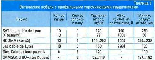
The parameters of optical cables with a profile core of various companies are given in Table. 3.
From the given data, it can be seen that OK manufactured by H0UMA (China) has the largest number of grooves - 12. This became possible due to an increase in the diameter of the profile rod, and the diameter of the cable itself lies within 12 ... 23 mm. The difference in the designs of such cables is explained by the laying conditions. As well as stranded cables. OK with profile cores can be both with metal reinforcing elements and without them. Without metal elements with several optical fibers in the groove, they are produced by the French companies Les cables de Lyon and SAT, as well as the Australian Olex Cables and others. Cables with profiled rods twisted around a central carrier are produced by a number of companies, in particular, the French company Les cables de Lyon mentioned above. They have profile rods with ten grooves in each. These rods are modules from which the cores of cables with 30, 50, 70 and 90 optical fibers are formed. These modules form a single layer layer. In OC with two layers of heave, such modules contain 120, 150, 160 or 210 optical fibers. The OC designs described are also called bundled cables. Most often they are used for laying in the ground. However, a number of firms, in particular Finnish Nokia and South Korean SAMSUNG, produce cables designed for suspension in power lines. In this case, the optical cable of the profile type is located inside the power electric cable. The cross section of one of these SAMSUNG cables is shown in fig. 4. This is a power cable made of aluminum conductors, inside of which there is a profile element with four grooves, each of which contains a module with six optical fibers
In addition to those described above, foreign companies also produce ribbon-type optical cables. In them, the reinforcing is the outer shell, which forms a hollow tube in which optical fibers are freely placed. An example is a two-fiber ribbon cable from SAMSUNG (Fig. 5). Ribbon cables are also manufactured by NTT (Japan) and ATT (USA). ATT cables consist of 12 modules arranged in a row in one plane, and each module contains 12 optical fibers. Ribbon cables are also produced, consisting of 40 or more optical fibers.
There are other designs of optical cables. For example, one of them is a strong tube in which OV is placed freely, without twisting. In such cables, the reinforcing elements - threads, rods, etc. - are located in the walls of the tube. Such cables are manufactured by ATT, NTT and Swiss VOLROLL ISOLA. On fig. 6 shows the cross section and appearance of such a cable manufactured by a Swiss company.
The specified constructions OK (tape and tubular) are intended mainly for laying inside objects. However, some of them can also be used for laying in the ground. In this case, additional measures have been taken in the OC design to increase the strength, and the inner cavity, in which the OF is located, is filled with a hydrophobic composition. Corresponding components and tools are produced for cable splicing. The splicing point is placed in cable sleeves. which have different designs. Couplings of the German company RXS are shown in fig. 7 and 8.
To connect optical fibers, the ends of the spliced cables at a length of 0.5 ... 1.0 m are released from the protective sheath and other auxiliary elements. Exempt from the protective sheath at a length of 20 ... 30 mm also OB. By shearing, flat ends of the OF are obtained. who weld. The welded OF is inserted into a heat-shrinkable tube with a rigid rod or placed in a V-shaped metal bracket. Then they fit in the sleeve as shown in these figures. All operations to remove the protective shell are OK. optical fiber, obtaining its flat end, etc. are made using a set of tools placed in a suitcase (Fig. 9).
With large amounts of fibers, the protective sheaths of the OF, as a rule, have the same color, and therefore it is difficult to identify the desired OF. To solve this problem, a special device is produced - an identifier. The principle of operation of the device is based on the perception of radiation from the side surface of the optical fiber when it is bent with a bend radius of 5...6 mm. On fig. 10, the master making the connection of the OB in the coupling holds such a device in his hands.
In conclusion, we note that the technology for the production of optical cables, as well as methods for their splicing, is constantly being improved. New, more advanced, more durable and resistant to thermal and chemical influences materials are being developed, which at the same time make it possible to create OCs of smaller diameter, weight and cost. Improvement of OK is also carried out in the direction of increasing their construction lengths up to 10 km or more, and underwater - up to 50 km. Author: O. Sklyarov, Moscow
Traffic noise delays the growth of chicks
06.05.2024 Wireless speaker Samsung Music Frame HW-LS60D
06.05.2024 A New Way to Control and Manipulate Optical Signals
05.05.2024
▪ Fiber Optic Ethernet Transceiver ▪ TB6865FG and TB6860WBG Wireless Charging Chips ▪ Pocket electronic encyclopedia
▪ section of the site for the radio amateur-designer. Article selection ▪ article Dust of distant countries. Popular expression ▪ article Who can fly farther: flying fish or flying squid? Detailed answer ▪ article Hematologist. Job description ▪ article New sound of 6AC-2. Encyclopedia of radio electronics and electrical engineering
Home page | Library | Articles | Website map | Site Reviews
www.diagram.com.ua |


 Leave your comment on this article: