Chips KR142EN12. Encyclopedia of radio electronics and electrical engineering

Encyclopedia of radio electronics and electrical engineering / Application of microcircuits
 Comments on the article
Chips KR142EN12A. KR142EN12B is an adjustable compensation voltage stabilizer. They are made by planar diffusion technology with insulation pn-transition. The stabilizer works with an external voltage divider in the measuring element, which allows you to adjust the output voltage in a very wide range - from 1,3 to 37 B. The regulating element of the stabilizer is included in the positive power cable. Output current (load current) - up to 1 A.
These microcircuit stabilizers are among the most "high-voltage" in the K 142 series. They are resistant to impulse power overloads, equipped with an output current overload protection system.
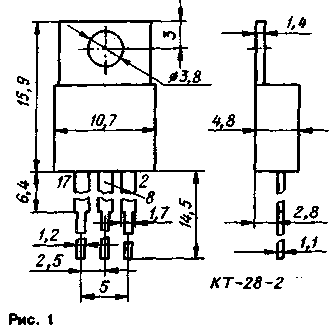
The instruments are packaged in a plastic case KT-28-2. On the side of one of the wide faces, an elongated heat-removing flange with a mounting hole is mounted in the case (Fig. 1). Weight of the device - no more than 2,5 g.

Electrical characteristics at T=25 deg
Minimum output voltage. V, its more, with an input voltage of 5 V and a load current of 5 mA ... 1,3
Minimum voltage drop. V, no more, at input voltage 18,5V...3,5
The instability of the output voltage by the input voltage, %/V, no more, with an increase in the input voltage from the initial value of 20 V, an output voltage of 15 V and an output current of 5 mA, for
KR142EN12A...0,01
KR142BN12B...0,03
The instability of the output voltage for the output current, % / A, no more, with an input voltage of 20 V, an output of 15 V and an increase in the output current from the initial value of 5 mA ... 0,2
Temperature coefficient of output voltage, %/'С, no more, at input voltage 5 V, minimum output voltage and output current 5 mA...0,02
Change in output voltage for 500 hours of operation, F, no more, at input voltage 45 V, output 15 V and output current 23 mA...1
Maximum permissible values of parameters
Input voltage, V... 5...45
Output voltage, V...37
Output current, A...1
Power dissipated by a microcircuit without a heat sink, W, at ambient temperature
(-10...+40)'С...1
+70 "C ... 0,7
Temperature operating interval 'С...-10...+70
The chip is designed to work with a heat sink; fastening to the heat sink - a screw with a nut. The power dissipated by a chip with a heat sink must not exceed 10 watts. A printed circuit board can be used as a substitute for a heat sink. The heat sink flange of the microcircuit is electrically connected to pin 2; this must be taken into account when mounting the heat sink on the board or on. casing of the device.
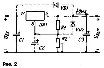
A typical circuit for switching on microcircuits KR142EN12A and KR142EN12B is shown in Fig. 2.

Resistors R1 and R2 form an external adjustable voltage divider, which is included in the measuring element of the stabilizer. The resistance values of the resistors must be related by the formula

where I.e.-current through the resistors R1 and R2 of the measuring element; the minimum allowable value of this current is 55 μA.
To reduce the background level at an output voltage close to the minimum, it is recommended to include a smoothing capacitor C2 in the measuring element of the stabilizer. The capacitance of this capacitor should be sufficient for effective smoothing (usually about 10 uF). The capacitance of the capacitor C1 is at least 0,1 μF, C3 is at least 1 μF.
With an output voltage exceeding 25 V, if it is possible to close the input circuit of the stabilizer, in the presence of capacitor C2, diodes V01 (KD510A) and VD2 (KD521A) should be inserted into the stabilizer; in the absence of capacitor C2, one diode VD1 is sufficient when the capacitance of capacitor C3 is greater than or equal to 25 microfarads. If the closure of only the output circuit of the stabilizer is not excluded, it is sufficient, in the presence of capacitor C2, to turn on only the diode VD2.
If there is a smoothing filter at the input of the stabilizer, and in the case when there are no switching devices between the output capacitors of the filter and the microcircuit, leading to a relatively slow increase in the input voltage, and when the length of the connecting conductors between the filter and the microcircuit does not exceed 70 mm, the input capacitor of the stabilizer can be the output filter capacitor. If the output capacitor of the filter is ceramic and its capacitance is less than -1 μF, or if it is aluminum and its capacitance is less than 10 μF, then it is necessary to turn on capacitor C1 (see Fig. 2) with a capacity of at least 0,1 μF, and it should be located at a distance no more than 70 mm from the microcircuit.
To maximize the stabilizing qualities of the microcircuit, it is necessary to connect the resistive voltage divider R1R2 and the output capacitor C3 as close as possible to its output, and mount the microcircuit in close proximity to the load.

Figure 3 shows the load characteristic of the stabilizer, illustrating the operation of the overload protection device (the zone of technological spread of parameters is shaded). The frequency response of the output voltage ripple smoothing factor is shown in Fig.4.

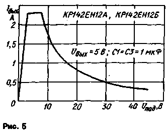
Figure 5 shows the dependence of the output current on the voltage drop across the microcircuit. The ascending section of the curve corresponds to the output of the microcircuits to the operating mode with the maximum output current. The second straight section is a working one.

When a certain threshold value of the voltage drop is reached, the protection system is triggered and the operating point moves to the third - the curvilinear section of the curve, which characterizes the mode of limiting the output current and the power dissipated by the microcircuit.
Authors: A. Nefedov, V. Golovina, Moscow; Publication: N. Bolshakov, rf.atnn.ru
 See other articles Section Application of microcircuits.
 Read and write useful comments on this article.
<< Back
 Latest news of science and technology, new electronics:
Machine for thinning flowers in gardens
02.05.2024
In modern agriculture, technological progress is developing aimed at increasing the efficiency of plant care processes. The innovative Florix flower thinning machine was presented in Italy, designed to optimize the harvesting stage. This tool is equipped with mobile arms, allowing it to be easily adapted to the needs of the garden. The operator can adjust the speed of the thin wires by controlling them from the tractor cab using a joystick. This approach significantly increases the efficiency of the flower thinning process, providing the possibility of individual adjustment to the specific conditions of the garden, as well as the variety and type of fruit grown in it. After testing the Florix machine for two years on various types of fruit, the results were very encouraging. Farmers such as Filiberto Montanari, who has used a Florix machine for several years, have reported a significant reduction in the time and labor required to thin flowers.
... >>
Advanced Infrared Microscope
02.05.2024
Microscopes play an important role in scientific research, allowing scientists to delve into structures and processes invisible to the eye. However, various microscopy methods have their limitations, and among them was the limitation of resolution when using the infrared range. But the latest achievements of Japanese researchers from the University of Tokyo open up new prospects for studying the microworld. Scientists from the University of Tokyo have unveiled a new microscope that will revolutionize the capabilities of infrared microscopy. This advanced instrument allows you to see the internal structures of living bacteria with amazing clarity on the nanometer scale. Typically, mid-infrared microscopes are limited by low resolution, but the latest development from Japanese researchers overcomes these limitations. According to scientists, the developed microscope allows creating images with a resolution of up to 120 nanometers, which is 30 times higher than the resolution of traditional microscopes. ... >>
Air trap for insects
01.05.2024
Agriculture is one of the key sectors of the economy, and pest control is an integral part of this process. A team of scientists from the Indian Council of Agricultural Research-Central Potato Research Institute (ICAR-CPRI), Shimla, has come up with an innovative solution to this problem - a wind-powered insect air trap. This device addresses the shortcomings of traditional pest control methods by providing real-time insect population data. The trap is powered entirely by wind energy, making it an environmentally friendly solution that requires no power. Its unique design allows monitoring of both harmful and beneficial insects, providing a complete overview of the population in any agricultural area. “By assessing target pests at the right time, we can take necessary measures to control both pests and diseases,” says Kapil ... >>
 Random news from the Archive Random news from the Archive Tantalum Innovation to Improve Fusion Reactors
20.12.2023
Engineers from the University of Wisconsin-Madison from the United States have presented an innovative method for lining the internal walls of a fusion reactor using tantalum. The proposed technology is designed to make the reactor more compact, as well as facilitate maintenance and repair processes.
A new technological advance in fusion reactor cladding opens up prospects for more efficient and compact use of this energy technology. Innovations like these make important contributions to the development of clean and sustainable energy sources, but also highlight the importance of further research into fusion energy.
The uniqueness of the method lies in the use of cold spraying of tantalum (a metal resistant to high temperatures) onto the surface of stainless steel. The material applied in this way is able to trap more hydrogen particles, which reduces the size of the fusion device.
Because ionized hydrogen particles sometimes escape from the plasma and are neutralized, some energy is lost. Therefore, creating a highly permeable surface of the reactor walls plays an important role.
The process of creating a coating using cold spray tantalum is similar to using a can of spray paint. Particles from the can are supersonically directed to the surface, flattened upon impact, covering the entire surface and maintaining nano-sized boundaries between particles. These microscopic boundaries prove effective in trapping hydrogen particles.
The researchers plan to use their new material in the WHAM facility. The experimental device, under construction near Madison, Wisconsin, will serve as a prototype for a future next-generation fusion power plant being developed by UW-Madison's Realta Fusion company. The WHAM experiment is conducted at the Physical Sciences Laboratory as a collaboration between UW-Madison, MIT, and Commonwealth Fusion Systems.
|
 Other interesting news:
▪ Mini computer Shuttle XPC DA320
▪ Acer to release 27-inch IPS panel monitor
▪ long-necked fossil
▪ Kevlar for battery
▪ Android 5.0 is expected in the second quarter of 2012.
 News feed of science and technology, new electronics
 Interesting materials of the Free Technical Library:
▪ section of the site for the Musician. Selection of articles
▪ article This mysterious gentleman High End. The art of audio
▪ article Why are the words bull and bee the same root? Detailed answer
▪ article Polenik. Legends, cultivation, methods of application
▪ article Infrared presence detector. Encyclopedia of radio electronics and electrical engineering
▪ article Electric machine rooms. Location and installation of electrical equipment. Encyclopedia of radio electronics and electrical engineering
 Leave your comment on this article:
Comments on the article:
To say more about
Good description! [up]
Vladimir
Right now I'm going to a psychiatric hospital, everywhere there are different pinouts en12, PPC. Even, at the same, Nefedov in his reference books. AAAAAAAAAAA. ![[cry]](https://diagram.com.ua/comments/smilies/cry.gif)
a guest
Why do different sources have different pinouts?
 All languages of this page
Home page | Library | Articles | Website map | Site Reviews

www.diagram.com.ua
2000-2024


 Arabic
 Bengali
 Chinese
 English
 French
 German
 Hebrew
 Hindi
Hindi Italian
 Japanese
 Korean
 Malay
Malay Polish
 Portuguese
 Spanish
 Turkish
 Ukrainian
 Vietnamese


 Leave your comment on this article: