|
|


 Arabic
 Bengali
 Chinese
 English
 French
 German
 Hebrew
 Hindi
Hindi Italian
 Japanese
 Korean
 Malay
Malay Polish
 Portuguese
 Spanish
 Turkish
 Ukrainian
 Vietnamese
|
ENCYCLOPEDIA OF RADIO ELECTRONICS AND ELECTRICAL ENGINEERING UMZCH soft start device. Encyclopedia of radio electronics and electrical engineering
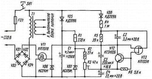
Encyclopedia of radio electronics and electrical engineering / Transistor power amplifiers The designers of sound amplifying equipment almost always face the problem of protecting the UMZCH and its power supply from impulse overloads at the moment the mains voltage is turned on. Descriptions of such devices have been repeatedly published on the pages of the magazine. However, some of them protect only the UMZCH itself, leaving the power supply unprotected, while others provide not a smooth, but a stepwise increase in the mains voltage. These shortcomings are not present in the device offered to the attention of readers, which implements the "soft" inclusion of the UMZCH. It does not have a switching relay, which made it possible to increase the reliability of the protection unit and reduce its dimensions. The schematic diagram of the UMZCH "soft" power-on device is shown in the figure. Transistor VT1 through the diode bridge VD1-VD4 is connected in series with the primary winding of the transformer T1 of the power supply. The choice of a MOSFET with an insulated gate is due to the high input resistance of its control circuit, which allows to reduce power consumption.
The control unit consists of circuits that form the voltage at the gate of the transistor VT1, and an electronic key on transistors VT2, VT3. The first circuit is formed by elements VD5, C1, R1 - R3, VD7, C4, setting the initial voltage at the gate of the transistor VT1. The second one includes elements VD8, R4, R5, C2, C3, which provide a smooth increase in voltage at the gate of transistor VT1. Zener diode VD6 limits the gate voltage of transistor VT1 and protects it from breakdown. In the initial state, the capacitors of the control unit circuits are discharged, therefore, at the moment of closing the contacts of the mains power switch SB1, the voltage at the gate of the transistor VT1 relative to its source is zero and there is no current in the source-drain circuit. This means that the current in the primary winding of the transformer T1 and the voltage drop across it are also equal to zero. With the arrival of the first positive half-cycle of the mains voltage, the capacitor C1 begins to charge through the circuit VD5, VD3 and during this half-cycle is charged to the peak value of the mains voltage. Zener diode VD7 stabilizes the voltage at the divider R2R3. The voltage on the lower arm of the tuning resistor R3 according to the circuit determines the initial gate-source voltage of the transistor VT1, which is set close to the threshold value of 2 ... 4 V. After several periods of the mains voltage, the current pulses flowing through the capacitor C2 will charge it to a voltage exceeding the cut-off voltage of the transistor VT3. The electronic key on transistors VT2, VT3 closes, and the capacitor C3 begins to charge through the circuit VD8, R4, R5, R3, VD3. The gate-source voltage of the transistor VT1 is determined at this time by the sum of the voltage on the lower arm of the resistor R3 and the gradually increasing voltage across the capacitor C3. As this voltage increases, the transistor VT1 opens and the resistance of its source-drain channel becomes minimal. Accordingly, the voltage on the primary winding of the transformer T1 gradually increases almost to the value of the mains voltage. A further increase in the gate-source voltage of the transistor VT1 is limited by the zener diode VD6. In steady state, the voltage drop across the VD1-VD4 bridge diodes and the VT1 transistor does not exceed 2 ... 3 W, so this practically does not affect the further operation of the UMZCH power supply. The duration of the most severe mode of operation of the transistor VT1 does not exceed 2 ... 4 s, so the power dissipated by it is small. Capacitor C4 eliminates voltage ripple at the gate-source junction of transistor VT1. created by pulses of the charging current of the capacitor C3 on the lower arm of the resistor R3. The electronic key on transistors VT2, VT3 quickly discharges the capacitor C3 after the UMZCH power supply is turned off or during short-term power outages and prepares the control unit for re-enabling. In the author's version of the protection device, an imported capacitor manufactured by Gloria (C1) was used, as well as domestic ones: K53-1 (C2, C4) and K52-1 (C3). All fixed resistors - MLT, tuning resistor R3 - SP5-3. Transistor KP707V (VT1) can be replaced by another, for example. KP809D. It is important that the resistance of its channel in the open state is minimal, and the source-drain voltage limit is at least 350 V. Instead of the KT3102B (VT2) transistor, it is permissible to use KT3102V and KT3102D, and instead of KP103I (VTZ) -KP103Zh. Transistor VT1 is equipped with a small heat sink with an area of 10...50 cm2. Setting up the device consists in selecting the optimal position of the trimmer resistor R3. Initially, it is set to the lower (according to the diagram) position and is connected through a high-resistance divider to the primary winding of the transformer T1 oscilloscope. Then the contacts of the switch SB1 are closed and, by moving the slider of the resistor R3, the process of increasing the voltage amplitude on the primary winding of the transformer is observed. The engine is left in a position in which the time interval between turning on SB1 and the beginning of the increase in the voltage amplitude on the T1 winding is minimal. If necessary, select the capacitance of the capacitor C3. The device was tested with a UMZCH layout similar in structure to the amplifier described in the article by A. Orlov "UMZCH with a single-stage voltage amplification" (see "Radio", 1997, No. 12, pp. 14 - 16). The voltage surge at the UMZCH output when the power supply was turned on did not exceed 1,5 V Author: M.Sirazetdinov, Ufa
Machine for thinning flowers in gardens
02.05.2024 Advanced Infrared Microscope
02.05.2024 Air trap for insects
01.05.2024
▪ Helicopter with muscle drive ▪ Artificial muscle based on natural proteins
▪ section of the site House, household plots, hobbies. Article selection ▪ article Automatic greenhouse. Drawing, description ▪ article Who was the first European to see the Victoria Falls? Detailed answer ▪ Article Project Manager. Job description ▪ article Retro: FET. Encyclopedia of radio electronics and electrical engineering
Home page | Library | Articles | Website map | Site Reviews
www.diagram.com.ua |

 Leave your comment on this article: