|
|


 Arabic
 Bengali
 Chinese
 English
 French
 German
 Hebrew
 Hindi
Hindi Italian
 Japanese
 Korean
 Malay
Malay Polish
 Portuguese
 Spanish
 Turkish
 Ukrainian
 Vietnamese
|
ENCYCLOPEDIA OF RADIO ELECTRONICS AND ELECTRICAL ENGINEERING Car audio: install yourself. Encyclopedia of radio electronics and electrical engineering
Encyclopedia of radio electronics and electrical engineering / Speakers It is often said that music in a car "by definition" cannot sound good, and therefore, they say, a simple radio and a pair of "columns" are enough. One can hardly agree with this. Specific features of the interior acoustics, of course, exist. But they should not be a hindrance to normal stereo sound reproduction, capable of unfolding the panorama and depth of the sound stage in front of the listeners, conveying the nuances of the performing arts. This article discusses the basic principles of the layout of car audio systems - from the simplest to the most complex, and also talks about the design, installation and configuration of some system components. When equipping a car with a new audio system or expanding the capabilities of a previously installed one, of course, it is not worth turning it into a concert hall on wheels. Moreover, it makes no sense to spend effort and money if the musical tastes of listeners are limited to electronic "pop": it does not require either a wide dynamic range or an accurate transmission of sound nuances. But for fans of traditional genres, all this is very important and opens up the widest field for creative activity. However, in any case, when installing equipment in a car, certain requirements must be strictly observed. And if you are offered to "quickly and efficiently install music" - do not believe it. This process (even copying the finished system) is not at all that fast. The main problem in creating a car audio system, contrary to popular belief among some music lovers, is not to achieve high power, low distortion and flat frequency response. The main task is to get a "high" and "wide" sound stage for the listeners sitting in front. The decision is directly related to the installation location of the front radiators. There is no need to think that passengers in the rear seats will have to be content with little - with the correct placement of the speakers, the sound will be balanced within the entire cabin. When creating a high-quality audio system, there are two creative approaches that can be taken. The first of these is "conceptual": they formulate the requirements for the system, select or manufacture the necessary components, and then - installation and configuration. This is an ideal, but expensive option, especially in terms of finishing. With this approach, the result, as a rule, is achieved on the first try, but this requires a one-time investment of significant funds and, most importantly, considerable experience and even intuition. Since there are no universal ready-made solutions in this regard, only professional installation studios can do such work. Achieving perfect sound also requires a lot of work. True, in the extreme case, one can be satisfied with the knowledge that it is extremely difficult to get a "bad sound" on good equipment... The second option is amateur, inexpensive, but not the worst. The system is created in the minimum configuration from the available components, and a good result is achieved by a reasonable layout and the use of proven solutions. The initial stage here depends only on financial capabilities, and experience will appear in the process of creativity. Then, as the requirements and practical skills increase, the system is "built up" to the desired level. This process is extended in time, and therefore the result will not appear immediately. True, to get a decent sound you have to work hard. Choose a system An amateur audio system at the first stage of development usually consists of a "head" apparatus - a radio tape recorder, a receiver with a CD or MD player - and a set of dynamic heads. They are given special attention in this article, but further, where it is not important, the radio will mean any of the signal sources. With any approach to the formation of an audio system, you must first select the signal source and the structure of the acoustic system (AS). Why is that? All of its components contribute to the formation of the integral quality indicator of a car audio system, taken as 100%, approximately 15% for the signal source, 20% for the amplifier, 30% for AC, 30% for installation (placement), cables and additional devices - 5%. Using, for example, a radio tape recorder with a built-in amplifier, its "contribution" increases to 20-25%, and AC - up to 40-45%. However, these figures refer solely to the sound quality, not to the price. With prices, the picture can be completely different. It's no secret that equipment prices are often determined by the popularity of the company and model, and by no means the real merits of the product. In any case, the choice of heads must be approached with maximum attention - "we are not rich enough to buy cheap things." Since it is not possible to independently change the main technical characteristics of a modern radio tape recorder (and it is hardly necessary, especially if it is not a fake), then its choice should also be taken seriously. When a system upgrade is intended to be carried out without replacing the head unit, it should initially be able to connect an amplifier to the line output. If you later plan to add a CD / MD changer to the system, it is advisable to choose a model that provides control of this device, since the choice of changer models with its own controller is limited. Note that some simple improvements are quite within the power of even not very experienced radio amateurs, and the cost savings can be significant. These improvements include the installation of linear input and output connectors in the radio, the introduction of external equalizers and filters into the path, the addition of output power indicators, etc. In fig. 1 shows an example of a simple refinement of the radio "Sony 1253" - the introduction of a line-in connector.
When choosing equipment, be sure to pay attention to its electrical characteristics. Nevertheless, the subjective perception of the quality (naturalness) of sound cannot be determined using physical quantities, and only listening can give an idea of how accurately the volume and spatial arrangement of instruments in the musical picture is transmitted. It is desirable that it be comparative (with other audio systems) and take place in the morning, while the auditory sensations have not yet become dull. It is best to compare the sound of acoustic instruments when played back, for example, from a CD, with the sound of the same instruments "recorded" in auditory memory. The undistorted output power of modern radio tape recorders usually does not exceed 10-12 watts per channel, even if the instructions indicate several times more power. The given value of the maximum power characterizes the dynamic properties of the amplifier and its ability to reproduce impulse signals, rather than the actual loudness. By the way, the real difference in sound between 4x30 and 4x40 W amplifiers is practically not noticeable. Therefore, when choosing dynamic heads to work with a radio tape recorder, the main parameter that you need to pay attention to is the level of characteristic sensitivity (or simply sensitivity). The larger it is, the less power is required to obtain the desired volume. Typical values for car loudspeakers are 88...91 dB/W1/2m. As for foreign-made heads, it is important to know under what conditions their parameters were measured. It is also necessary to take into account the fact that the components of electroacoustic equipment, each in its own way, color the signal. Since the mutual influence and coordination of equipment has not yet been fully studied from the point of view of psychoacoustics, even if all the requirements of the standards (which are quite vague, by the way) are met, it is better to listen to the selected components "in conjunction". It should also be remembered that the sound of the equipment on the stand in the store and in the car can differ markedly. Why is this happening? Some theory The car interior space is not acoustically adapted for high-quality sound reproduction - the interior volume is extremely small. Several obvious conclusions follow from this circumstance: 1. It is almost impossible to meet the main condition for providing stereophonic sound - the relative position of the listeners and the loudspeakers of the acoustic system along the vertices of an equilateral triangle. In addition to the difference in sound intensity, there is a time shift between the left and right channel signals, which causes the apparent sound sources (PSS) to shift relative to their true position. This effect is especially noticeable for mid-frequency signals. 2. It is difficult to ensure the necessary distance of the listener from the loudspeakers. And when working in the near zone of radiation, the loudspeaker can no longer be considered as a point source, which leads to specific interference distortions at medium frequencies (at high frequencies, this effect is weakened due to the small size of the emitters). 3. Due to the small volume of the cabin at low frequencies, a fairly homogeneous sound field arises (this is true with a small caveat, the essence of which is explained below). However, the presence in the cabin of unevenly located absorbing and reflecting surfaces (glasses, upholstery, passengers) does not allow one to confidently predict its acoustic properties at medium and high frequencies. In addition, these surfaces provide varying degrees of reflection and absorption within the frequency range - soft seats and door upholstery effectively absorb low and medium frequency vibrations, and high-frequency sounds are perfectly reflected from the glass. As a result of the indicated frequency response of the cabin at medium and higher frequencies, it has unevenness, sometimes significant, and the nature of the unevenness depends on the choice of the measuring point. In addition, there are two more aspects, not so obvious, but related to the small volume of the cabin and its geometry: local unevenness in the frequency response caused by resonance phenomena, and the rise in the frequency response at lower frequencies. These factors together form the transfer characteristic of the cabin. So, due to the presence of relatively parallel surfaces in the cabin (side walls, floor and ceiling), conditions are created for the occurrence of standing waves. Of practical importance are only oscillations at subharmonics and the fundamental frequency, the intensity of the remaining components is very small. In reality, due to the presence of obstacles in the form of seats and passengers, most of the resonances are suppressed, and only the transverse one is clearly expressed. It manifests itself at those frequencies where the cabin width corresponds to half the wavelength (for most cars - 120 ... 150 Hz). To the ear, this manifests itself in the form of an unpleasant hum and "mumbling". As a first approximation, we can assume that the transverse resonance frequency is equal to Fr=Vs/2W, where Vs=340 m/s is the speed of sound; W - interior width. The harmful effect of resonance can be reduced by using soft door lining, but it can be completely suppressed only by correcting the frequency response of the tract. So, in the author's car (VAZ-2107), the replacement of regular smooth facings with soft velor ones reduced the "hump" in the frequency response from 8 to 6 dB, and the resonance frequency decreased from 140 to 130 Hz due to a decrease in the quality factor of the oscillatory system. The rise in frequency response at lower frequencies has a similar explanation. For signals at frequencies whose wavelength is commensurate with the maximum size of the cabin (usually its length), the cabin is the equivalent of a second-order acoustic low-pass filter, the frequency response of which, below the cutoff frequency, has a slope of about 12 dB per octave. In the first approximation (without taking into account the absorption in the cabin and the final rigidity of the body panels), we can assume that the cutoff frequency is Fc= Vs/2Lmax (here Lmax is the maximum size of the cabin). At this frequency, the rise reaches 3 dB, and below - at F<Vs / 4Lmax - it disappears. Thus, the rise in the frequency response of the cabin in the audible frequency range is approximately 12 ... 18 dB. Due to the fact that the acoustic properties of the interior are not ideal, the real figures are somewhat different from the theory - for the "classic" body, the frequency Fc is approximately 60 Hz, for the "chisel" - 55 Hz and for the "station wagon" bodies - 45 ... 50 Hz . Two of the possible variants of the transfer characteristic are shown in Fig. 2. Obviously, the sound of the same dynamic heads in different salons will be completely different.
Based on the previously discussed factors, the choice of a place in the cabin for installing loudspeakers is of paramount importance. Moreover, the choice of the number of bands and frequencies of the section depends on the place of their installation. We place Car loudspeakers are usually not very sensitive, but have good frequency response, a wide polar pattern, and a balanced sound. Given that the capabilities of wideband and coaxial drivers are still limited, the best results can only be achieved when using a multi-way distributed front speaker. It is also important to correctly determine in which places in the car interior you need to place bandpass radiators so that they work with maximum efficiency. Two-way front speakers are the most common today, but in high-quality audio systems they are gradually being replaced by three-way ones. The principles of head placement were briefly outlined by the author in [1], but the experience accumulated since then and the exchange of opinions in [2, 3] require some adjustments to be made to them. To get a high sound stage, it is easiest to place the radiators as high as possible. The dashboard allows this to be done, but regular seats for installing heads are usually limited to 10 ... But the installation of mid-range heads in this place also has serious drawbacks. The main one is the binding of the sound to one side of the cabin due to the unacceptably large difference in the path of the sound wave from the left and right emitters. The fact is that of all domestically produced cars, only Moskvich-13 can use the regular places reserved for loudspeakers for its intended purpose. It should be noted that this solution cannot be considered the most successful. It is no coincidence that designers are forced to look for other places to install loudspeakers. Traditionally, low-frequency, full-range or coaxial loudspeakers are placed in the front doors of the car. Their relatively large internal cavity contributes to the effective reproduction of low frequencies with an almost finished acoustic design. Usually, in phonograms, the sound signals of the left and right channels in this frequency range are in phase and have almost the same intensity. Therefore, from the heads mounted on the plane of the door lining, the wave front at frequencies of 100 ... 150 Hz reaches the opposite head with partial reflection compensation. To reduce this phenomenon, the heads should be turned up in the middle of the ceiling above the front seats. This option is most rational when using a two-way front speaker with a relatively high crossover frequency (5 ... 7 kHz). The effect of such compensation largely depends on the location of the low-frequency radiators in the doors and the design features of the cabin. For example, a high tunnel and an extended dashboard console ("beard") somewhat weaken this effect, and then the installation of heads "on a plane" is quite acceptable. This option is most rational in a two-way system with a band separation area of 1 ... 1,5 kHz. The radiation pattern of the heads in this frequency band is quite wide, however, in two-way systems with a low crossover frequency, it is necessary to use high-power RF heads with a reduced natural resonance frequency. In addition, to effectively reduce the emission of frequencies close to the resonant one, it is necessary to use a high-order high-pass filter or special corrective circuits. To install the heads in the door, it is often necessary to make special panels (podiums) or ring linings that increase the actual depth of the compartment. In addition, it is necessary to take measures to dampen vibrations of panels and door mechanisms. The installation of woofers in cases under the front seats with forward-up radiation eliminates the effect of compensation and reduces the time delay, reducing the effect of "binding" the apparent sound source to one side of the cabin. Due to a certain concentration of low frequencies in the front part of the cabin, the sound pressure increases in the region of 200 ... 400 Hz. At the same time, the emission band in this case is limited from above by a frequency of about 2...3 kHz. Therefore, such an arrangement of radiators requires either the use of a low crossover frequency, or a transition to a three-way speaker. As an example, in fig. 3 shows the frequency response for the 25GDNZ-4 dynamic head in a housing (with a phase inverter) installed under the front seat of the Moskvich - 2141. According to passport data, the decrease in frequency response for this head begins at frequencies above 125 kHz. Such a deviation of the frequency response from the passport one can be explained by the presence of an obstacle (seat cushion) in the near radiation zone. For a similar speaker under the front seat of the VAZ-800, but with a radiation direction close to horizontal, the frequency response dip is shifted to the region of 1,5 ... 3 Hz and has a smaller value. These frequencies correspond to a wavelength of about 2107 ... 500 m, which is in good agreement with the dimensions of the cavity, limited by the dashboard and console.
Installing the heads in kickpanels with their radiation axis oriented upwards - towards the center of the cabin minimizes the difference in the signal path from the left and right emitters, which practically eliminates the binding effect. Contrary to expectations, the sound stage does not descend, but rather rises to the level of the windshield. Unfortunately, in most cases, it is not easy to organize a decent acoustic design: the maximum possible volume of cases does not exceed, as a rule, two or three liters. Therefore, this option is applicable mainly to the mid-range heads of three-way speakers. Since at frequencies above 1 kHz, the radiation pattern of the emitters is quite individual, there are no unambiguous recommendations on the orientation of heads on kickpanels - it all depends on specific conditions. An experiment is needed here. Another, no less interesting option for placing midrange emitters. used in his installation S. Klevtsov. Masrom dome heads are installed on the cross beam under the front seats of the Svyatogor and are oriented towards the windshield. This solution reduces the relative difference in the path of the sound wave from the left and right emitters, which makes it possible to practically eliminate the effect of sound binding to one side of the cabin. For a preliminary assessment of the selected installation site and the choice of orientation of the bass and midrange emitters, it is convenient to use broadband heads with a power of 3 ... 5 W, mounted on small reflective panels. They are connected to the radio through the simplest high-pass filter (a non-polar oxide capacitor with a capacity of 100 microfarads or two polar 220 microfarads connected in anti-parallel) and the location and orientation are selected, achieving the required width and height of the stage. In the manufacture of enclosures for midrange drivers, it is useful to clarify the orientation in relation to specific heads, taking into account the characteristics of their sound. High-frequency heads for any variant of the construction of the front speakers are installed on the front pillars, on the upper front corner of the door or on the instrument panel. In the first and second cases, both the direct signal and the signal reflected from the glass are used; in cases of installation on racks, only the radiation reflected and scattered from the windshield is used. Also known is the option of installing high-frequency emitters near the rear-view mirror (using the signal reflected from the glass). When choosing a place for high-frequency heads, it must be borne in mind that at a low crossover frequency, their radiation has a direct effect on the formation of the sound stage and orientation requires careful tuning; at a crossover frequency above 5...6 kHz, the effect of orientation will be reduced. In any case, when installing them, it is necessary to provide for the possibility of adjusting the orientation during the final setup of the system. In the kit of most car "tweeters" there are installation parts necessary for this. Solving questions related to the use of a subwoofer and rear speakers should only be done after setting up the front speaker. The formation of a sound image without a rear channel will be incomplete, so you should not neglect it. Its main purpose is to create a "hall effect" by simulating the reflected sound. The rear channel signal spectrum for this should be limited to a frequency band of approximately 500 ... 2500 Hz, in accordance with the diffuse sound spectrum, and the signal level should be low. Using the rear channel allows you to mask some of the shortcomings in the sound of the front speaker. The most impressive results are obtained when using a difference signal in the rear channel. To implement this method, in the simplest case, you can use the back-to-back connection of two rear heads between the outputs of the amplifiers of the left and right channels through a band-pass LC filter (Huffler circuit). However, the best results are achieved when using additional rear channel signal processing, the device of which is described in [4]. The main prerequisites for further improvement of the method are also outlined there. Full reproduction of low frequencies requires acoustic design of a significant size, therefore, in almost all mobile installations, the frequency range of the main channels is limited from below by a frequency of 70 ... 120 Hz. To emit lower frequencies, you have to use a subwoofer. Since radiation is non-directional at the lowest frequencies, the choice of location for the subwoofer is a matter of system layout. Most often it is installed in the trunk, although an unjustified upward extension of the frequency band can be accompanied by a bass "delay" effect. About noise and vibration The problem of noise reduction is especially acute in the car. Even in a well-designed body from an acoustic point of view, vibrations occur during movement, both from the vibration of the engine and transmission, and from the vibration of the wheels on the road. At the lowest frequencies, the low rigidity of the body affects, which causes vibrations of the panels and the roof. In this case, the main noise power is concentrated in the region between the lowest frequencies and the lower boundary of the middle frequencies. In motion, although the noise is "organized", but at a constant speed it is quite homogeneous and, thanks to the selective properties of hearing, it can be tuned out. With the exception of the consequences of shocks and impacts caused by the deplorable state of the roads, the remaining noise components can be significantly attenuated with the help of well-executed soundproofing of the cabin (wind whistle and tire rumble are not considered - at this speed there is no time for music). To absorb road noise, the material should be applied to the floor and fireproof bulkhead and in the area of the wheels. But since the traffic cycle familiar to residents of large cities is “we drive a meter, we stop for two”, the problem of sound insulation is not so acute for them. In addition to soundproofing, designed to block the path to the interior of external noise, vibration damping of large panels (roof, doors) is used to eliminate possible overtones during the operation of the audio system. If the power of the amplifiers is low, then in most cases this measure is not required, however, maximum attention should be paid to eliminating resonances and vibrations of decorative interior parts, since even at relatively low power they generate rattling and overtones that are more unpleasant to the ear than traffic noise. Particular attention should be paid to the panels next to the loudspeaker heads or to the panels that are used as part of the loudspeaker enclosure. If it is not possible to completely cover large panels, it is better to apply a damping layer on their middle part, as the least rigid. Resonances are usually eliminated by covering a quarter of the area or more. The main places of processing on the example of the body of the "classic" VAZ are shown in fig. 4. This is the "minimum" program; the "maximum" program also includes the processing of the roof, trunk hoods and engine compartment, wheel arches.
When starting to soundproof and vibration damping the car interior, it is useful to be guided by the following rules of thumb:
Vibration damping of body panels is improved using various materials - both specially designed for this purpose and substitutes. A common property of such materials is that they have a high internal viscosity. Apply sheet materials of various thicknesses, as well as mastics or foaming aerosols. Sheet materials look and feel like rubber. Dynamat has the greatest damping and at the same time soundproofing effect, but it is not cheap, and when processing a car “in full”, the costs can become commensurate with the cost of a used domestic car. Therefore, motorists are trying to find alternative solutions. Satisfactory replacement of imported vibration-damping materials: "Shumizol", "Liplen", "Vizomat", "noise-insulating rubber mastic" - all of domestic production and quite affordable. For filling the cavities of the "torpedo" and some body parts, the construction foam "Macroflex" is perfect. However, it must be taken into account that it increases significantly in volume and is therefore unsuitable for filling closed cavities. Well-known to motorists (one might say, classic) soundproofing material is linoleum. In building materials stores, the remnants of linoleum are usually sold at a significant discount. However, its choice should be approached with caution. Woven-based linoleum has excellent soundproofing properties, but its base is hygroscopic and requires additional anti-corrosion treatment of the underlying surfaces. Modern types of foamed linoleum without a base are non-hygroscopic, but their sound absorption is somewhat worse. However, no one bothers to put a double or triple layer in important places! Another material similar in structure that has become widespread in recent years is polyethylene foam. It is an excellent sound insulator (the degree of sound absorption at a thickness of 10 mm is 60%). In addition, it is absolutely non-hygroscopic, does not rot and is inexpensive. To eliminate squeaks and vibrations of the door lining, you need to abandon unreliable plastic caps and install the lining on self-tapping screws. If necessary, thin strips of foam rubber or polyethylene foam are glued at the points of contact between the lining and the door panels. For this purpose, strips of self-adhesive foam rubber, designed to seal window frames, are well suited. You should choose non-hygroscopic grades of foam rubber, in which the structural pores do not open outward. When installing the head in the door, its internal mechanisms require processing - it is necessary to exclude touching its surface with rods and drives. For this purpose, PVC pipes and plastic sleeves can be used. In addition, careful adjustment eliminates the backlash of mechanisms and rubber cords-braces. You can determine the required amount of work, and then the quality of the interior processing, in a very simple way. Through the speakers installed in the passenger compartment of sufficient power (at least 20 W), a signal from a 3-hour signal generator is reproduced. The generator is smoothly tuned in the frequency range of 50 Hz ... 2 kHz. Resonant vibrations of body elements at infra-low and low frequencies are felt tactilely, at higher frequencies - aurally by the appearance of rattling overtones. Carrying out work to improve noise and vibration isolation in the car should be combined with the installation of power and signal wiring of the audio system, especially since there are a number of requirements for installation, which must be met even when installing the simplest radio, not to mention high-level systems. Otherwise, many jobs will be fraught with unnecessary difficulties that can be avoided. Power wiring For low-power devices (radio and equalizers, for example), you can usually use existing power wiring. Separate amplifiers (increased power) consume much more current. The wiring in the car is not designed for this. In addition, since all of it is assembled in wiring harnesses, there is a danger of mutual influence of "automobile" and "sound" circuits. Based on this, it is recommended to lead the positive power cable of the amplifier directly to the battery, even if the radio is the only component of the system. The negative power wire of the system is usually connected to the car body. It should be as short as possible, and its cross section should not be less than the cross section of the positive wire. The connection to the body should be made through the unpainted metal of the body. If it is galvanized, one of the connection points provided by the manufacturer must be used in order to avoid interference in the system. When the car body is not new, the transition resistance of the welds increases, therefore, in order to reduce the voltage drop, in this case, the negative wire should also be connected directly to the battery terminal. When installing power wiring, you must first of all remember to comply with safety requirements. Consideration: Will the wire need to be routed around corners, through doors, or in the engine bay? These kinds of problems place special demands on the choice of wiring. It must be flexible, with thick insulation, not soften at high temperatures and not crack at low temperatures. This is especially true for sections of power wiring laid in the engine compartment. The use of rigid wire with easily cracked insulation can be a fire hazard. To prevent fire in the event of a short circuit in the power wire, a fuse must be inserted into the circuit. It is installed in a break in the power wire near the positive terminal of the battery. The fuse holder must be securely fastened. The fuse operation current is chosen 20 ... 30% more than the maximum current consumed by the system. This does not interfere with its normal operation, but guarantees the immediate shutdown of the circuit in the event of a short circuit. When laying the power wire in the engine compartment, you can drill a hole in the engine shield or use the ones already available near the steering column and mounting block. Passing wire through holes with sharp metal edges requires the use of rubber seals. In the engine compartment, it is desirable to additionally protect the wire with a corrugated tube. It should not be stretched, and in free places it must be secured with mounting clamps or strapping. When choosing power wires, the features of a particular type are taken into account, paying special attention to their cross section. It is traditionally measured in units of American Wire Gauge (AWG), or simply "gauge" (gauge). Wires and accessories for them (distributors, connectors, fuse holders, etc.) are produced all over the world under this marking. To find out the wire size for your system, you first need to determine the maximum current draw and cable length. Then use the information in Table. 1 [5], used by RASKA (Russian Association of Competitions and Competitions in Car Audio) when assessing the quality of the installation.
To improve the energy performance of the on-board power supply system, a capacitor is connected in parallel with the battery, and it is installed as close as possible to the most critical power consumer in the audio system. This will compensate for the voltage drop that occurs on the connecting wires at power peaks. The installation of a capacitor is justified even when using a radio without additional components - in this case, the reproduction of peak signal levels is significantly improved, the sound ceases to be "clamped". To determine the capacitance of a capacitor, an empirically verified ratio is used - 1 farad per kilowatt. For example, for a system with a power consumption of 100 W, a 100 uF capacitor will do. For the radio, a capacitor with a capacity of 000 ... 47 microfarads is enough. Some audio manufacturers, such as Phoenix Gold, make high-capacity capacitors specifically designed for car audio systems, but they are prohibitively expensive. In practice, with amplifier power up to 68 ... 000 W, conventional high-capacity oxide capacitors or a battery of smaller capacitors connected in parallel can be successfully used. Using capacitors of wide application for this purpose, it is necessary to focus on the maximum temperature allowed for them - in summer in a car standing in the sun, the temperature can reach 50 ... 100 "C. Preference should be given to capacitors that have a safety valve (plug), in extreme case - with a notch on the body. Taking into account changes in voltage in the vehicle's on-board network, the operating voltage of the capacitors must be at least 16 V. However, the following circumstance must be borne in mind. If the voltage regulator in the on-board network fails, it can rise from 14 to 18 ... 20 V. Therefore, to prevent breakdown of capacitors, the operating voltage should be selected large - 20 ... 25 V. Direct charging of a high-capacity capacitor from the on-board network is dangerous. Therefore, to limit the current, the initial charging must be carried out through a resistor with a resistance of 10 ... 20 Ohms or, more simply, through an incandescent car lamp. When the lamp goes out, further charging can be carried out "directly". If the car owner disconnects the battery for the night, it is recommended to use a simple device to charge the capacitor, the circuit of which is shown in fig. 5.
The switch is used of any type, it is only important that it is designed for the maximum current consumed by the system. Signal circuits and noise The rules for wire selection and installation of power circuits that were discussed are also valid for high-current signal circuits. So, when choosing a wire section for connecting dynamic heads, you can successfully use the above table, reducing the current according to the number of amplifier channels. As a rule, the wires offered by the manufacturer with dynamic heads are in most cases completely unsuitable for our purpose. The resistance of a double wire 2 m long can sometimes reach 0,5 ... 0,7 ohms, which leads to noticeable power losses in the radio amplifier. Therefore, it is not worth saving on "column" wires either. Particular reliability of the wire is required when installing dynamic heads in a car door. In no case should the wire be passed "under the upholstery" - it must pass through the holes in the metal of the door and rack, necessarily protected by a guide tube. These measures ensure that the wire is not pinched, kinked or looped. Loudspeaker wiring is usually not a problem. The exception is some types of modern foreign-made cars. They are so saturated with electronics that if the installation is unsuccessful, the pickups on the wires of the audio system can be audible. To avoid this, you should first clarify the location of the on-board computer and the location of the cables through which data is exchanged. Installation of interconnect signal wiring significantly affects the quality of sound reproduction. The main problem with most audio system layouts adopted today is the long interconnection cables. Most often, a CD changer is placed in the trunk, and the signal for adjustment and further amplification is fed to the input of the radio installed in the instrument panel. If there is an additional amplifier, it is usually also located in the trunk, so the cable length is at least doubled. Self-capacitance at this length can already affect the transmission of high frequencies. Therefore, the input impedance of car amplifiers and linear inputs of radio tape recorders is very low (about 10 kOhm). Despite this. the best way out is the rational layout of the system and the use of interconnect cables of the minimum required length. Hidden "out of sight" excess cable can degrade the reproduction of higher frequencies. To solve the problem of pickups, two methods are most widely used - increasing the output voltage of signal sources and using differential (balanced) communication lines. According to how the linear outputs of the signal source and the input of the amplifier are made, the type of interconnections is also chosen. The use of balanced lines is typical for components of a high price category and guarantees excellent noise immunity. The signal voltage is supplied to the inputs of the differential amplifier in antiphase, and the interference is in phase and is suppressed (Fig. 6).
However, this is true only if the pinia is completely symmetrical. Using a balanced input with an unbalanced output (and vice versa) negates all the advantages of this scheme. In this case, the best solution is to use a balancing device, the most elegant is a transformer, but it may be too expensive to ensure the required quality indicators. The main sources of interference in a car are the ignition system, which creates cods, and the generator, the interference from which is felt as a tonal variable frequency. Interference from the ignition system cannot be completely eliminated, but can be significantly reduced. In cars with a traditional (contact) ignition system, the use of an ignition distributor with a built-in noise suppression resistor or high-voltage wires with distributed resistance can significantly reduce the power of interference. A shielded cable will further reduce the level of interference. Alternator noise can be caused by poor collector and voltage regulator conditions. But even if it is in perfect condition, if there are several components in the system, interference can be heard due to improper grounding. If there are multiple ground points in an audio system, then a parasitic loop will form when the components are connected together. That is why it is impossible to allow the common wire of the components to be connected to each other through interconnect cables. For the same reason, the screen should not serve as a signal conductor. It is easy to implement this condition: when installing the connectors on the cable yourself, the screen is not soldered on one side. When using pre-made cables, the lugs of the RCA plug can be insulated from the connector housing with a thin layer of electrical tape. The same method will allow you to find out from which side it is better to isolate the screen - from the side of the signal source or from the side of the amplifier. If this measure does not help, it remains to use a single ground point for the entire system, best of all - on the negative terminal of the battery. TYPES OF ACOUSTIC DESIGN AND CHARACTERISTICS OF HEADS In order for a stereo speaker in a car to deliver high-quality sound, it must be properly designed and carefully installed. This section provides brief recommendations that will help you avoid the most common mistakes that can nullify all design tricks. Any dynamic head requires a certain acoustic design. You can select the heads for the existing type of design, or, conversely, calculate the necessary acoustic design for those available. The easiest way is to install the dynamic heads in the places provided for this purpose. This is what beginner car lovers usually do. However, car designers' ideas about acoustic design can be very different from the generally accepted ones. As a rule, regular places in the front doors are designed for the installation of small heads with a diameter of 7.5 ... 10 cm. And the direction of their radiation can only be explained by a strange whim of the designer. Domestic cars are especially unsuccessful in this regard, in most of which the installation of front speakers is not provided at all (or is contraindicated). Therefore, the owner, willy-nilly, has to show considerable ingenuity in the design and manufacture of speakers. It must be remembered that as the complexity of acoustic design increases, its "sensitivity" to errors and miscalculations also increases. Therefore, do not blindly believe the average characteristics of the dynamic head given in the passport (the actual ones may differ by 50 ... 80%), but measure the resonant frequency, quality factor and equivalent volume of a particular instance on your own. Methods for measuring these parameters have been repeatedly described in the journal "Radio", for example, in [6], and in the literature. In automotive speakers, of the many types of acoustic design, the "acoustic screen" (Infinity Buffle) and "open case" (Free Air) are most widely used. The first of these is mainly used for midrange and wideband heads, on which most car audio systems are built; the second is sometimes found in subwoofer designs. An acoustic resistance panel (PAS. Aperiodic Membrane) can also be considered an open acoustic design option, but it is used very rarely. The main reasons for this are the lack of a reliable calculation method and the complexity of "piece" production. The frequency response of the dynamic head in the "open" design falls off in the low-frequency region with a steepness of 6 dB per octave, which is similar to a first-order acoustic high-pass filter. Theoretically, the frequency response at lower frequencies should have a rise (taking into account the transfer characteristic of the cabin), but in reality this does not happen. The maximum that can be expected in this case is a small "hump" in the region of 50...70 Hz. The calculation is usually not made, relying on the versatility of dynamic heads and installation in regular places. However, when choosing heads for a particular open design option, it is worth considering their characteristics. The main advantages of this design are a smooth phase response and the absence of an overshoot at the transient, which has a positive effect on the "musicality" of playback, as well as high efficiency. The disadvantage is the weakened reproduction of lower frequencies (more on this later). Therefore, the acoustic screen in its pure form is practically not used for the design of low-frequency heads. The second place in terms of prevalence was shared by the "closed box" and the phase inverter (FI, Vented Box, Ported Box, Bass Reflex), used both for the mid-bass section and in subwoofers. In addition, a closed case of small volume is also used in the design of mid-frequency and broadband heads, installed together with low-frequency ones. Isolation of the rear side of the cones from the radiation of a powerful woofer eliminates the overload of their moving system and intermodulation distortion. The closed case is similar to the second-order high-pass filter. Its main advantages are excellent coupling with the transfer characteristic of the car interior (which is a second-order low-pass filter), which theoretically allows you to get a flat frequency response, and an excellent impulse response. The disadvantage is low efficiency, which requires the use of sensitive heads or increased amplifier power. A case with a phase inverter is an analogue of a fourth-order high-pass filter, but in fact, depending on the design and settings, it can be close to the third order. Therefore, even taking into account the transfer characteristic of the cabin, a flat total frequency response is unattainable. Advantage - high efficiency. The impulse response is somewhat worse than that of a closed case. The main disadvantage is that below the frequency of the phase inverter, the amplitude of the diffuser oscillations is limited only by the rigidity of the suspension, so damage to the head is possible. To prevent this in the signal path, it is necessary to apply a filter that cuts off infra-low frequencies (subsonic filter). Such exotic types of acoustic design as "passive radiator" (Passive Radiator) and "strip" loudspeaker (Bandpass) with HPF properties of the fourth - eighth orders. used exclusively in subwoofers. The advantage of a bandpass loudspeaker is high efficiency, while the impulse characteristics are very mediocre and deteriorate with increasing order. The listed types of acoustic design are practically limited in car acoustic systems. An acoustic horn and a labyrinth, due to their considerable size, are a rarity even in "home" acoustics, and it is simply impossible to use them in a car. The exception (extremely rare) is only horn "tweeters". The methodology for calculating phase inverters and passive radiators can be found in [7]. However, the graphical calculation methods proposed there are laborious and not very accurate. It is more convenient to use modern calculation programs, many of which allow you to take into account the transfer characteristic of the cabin. This allows you to evaluate the effect of all parameters on the frequency response of the system. Acoustic design software can be found on the Internet (eg [8-11]). With the proliferation of acoustic design software, design complexity is no longer a limiting factor, but. as the number of "degrees of freedom" grows, for complex designs of low-frequency loudspeakers, it is necessary to control the parameters of the dynamic heads and adjust the finished product. Therefore, the most widespread in amateur designs are closed cases and with phase inverters. For the same reason, strip radiators in amateur installations are found, as a rule, in the form of finished products with an order no higher than the fourth. More complex designs are rare even among industrial and professional designs. Somewhat great prospects in amateur installations have a passive radiator, in some cases it may be preferable to a phase inverter. When using a dynamic head with a large diffuser stroke to eliminate air noise in the phase inverter tunnel, its cross section and length have to be significantly increased, while the length of the tunnel may exceed the dimensions of the case. In this case, it is more convenient to switch to using a passive radiator. In fact, this is a kind of phase inverter. in which the mass of air in the tunnel is replaced by the mass of the mobile system of the passive radiator. A separate dynamic head can be used as a passive radiator. Usually in amateur designs it is used without a magnetic system, but it is better to use a full-fledged head. In this case, it is already possible to tune the PI not only mechanically (by changing the mass of the moving system of the passive radiator), but also electrically - by changing the resistance of the resistor connected in parallel to the voice coil of the passive radiator [12]. This unconventional method allows you to change the characteristics of the system over a wide range. On fig. Figure 7 shows the experimentally obtained frequency dependences of the total electrical resistance modulus of the 25GDNZ-4 dynamic head in a 7-liter closed case with a 25GDN4-4 passive emitter. As can be seen from the figure, by introducing a shunt of the passive head Rsh, it is possible to adjust the characteristics of a loudspeaker with a phase inverter.
On fig. 8 shows the results of modeling the frequency response of such a speaker with the JBL SpeakerShop program, taking into account the transfer function of the "classic" interior of a VAZ car. Curve 1 - frequency response for a closed case, curve 2 - for a phase inverter. Sections of the graphs for frequencies below 30 Hz have no physical meaning, since the simulation of the transfer function does not take into account the real properties of the passenger compartment.
The choice of acoustic design is directly related to the characteristics of the dynamic head, primarily with its full quality factor QK. The total quality factor of the head is considered low if it is less than 0.3 ... 0,35; high - more than 0,5 ... 0.6. For operation in a closed case, heads with a quality factor of not more than 0.8 ... 1 are suitable, for operation with a phase inverter - less than 0,6. Open acoustic design is recommended for heads with a total quality factor of more than 1. In addition, it is necessary to know the equivalent volume for the head and its natural resonant frequency in open space Fv It determines the lower limit of the reproducible frequency band. Since all types of acoustic design, except for open ones, increase the resonance frequency of the head, knowing the equivalent volume, it is possible to estimate the required volume of the cabinet based on the allowable degree of its increase. The suitability of the head for reproducing lower frequencies can be assessed by the empirical ratio Fv/Qk. If this ratio is 50 or less, the radiator is designed to work in a closed case, if 90 or more - in a phase inverter. From the same positions, for work in an open design, it is necessary to choose a head with a high total quality factor (not less than 0.5) and a resonant frequency of 40 ... 50 Hz. However, in this case, other factors must be taken into account. When choosing acoustic design, we recommend focusing on the resulting quality factor in the range of 0.5 ... 1,0. If it is equal to 0,5. then the best impulse response is achieved, if 0,707, then the frequency response is the smoothest. With a quality factor of 1, a rise of about 1.5 dB appears at the cutoff frequency. perceived by the ear as a "biting" sound. With an increase in the quality factor, a pronounced resonant "hump" appears on the frequency response, giving a characteristic "humming" overtone. However, in some cases, taking into account the nature of the musical material and the transmission characteristics of the cabin, this may be useful. The open design of a car speaker is created, as a rule, by interior panels. Their characteristics are far from necessary, and changes are almost impossible. Therefore, one has to put up with the deterioration of the frequency response in the low-frequency region in advance. The area of an ideal acoustic screen that does not affect the reproduction of frequencies above the resonant frequency of the head Fs. is S = 0,125(Vs/FsQk)2(m2). where Vs = 340 m/s is the speed of sound; Qk - total quality factor of the head. Since the area of a real acoustic screen is much smaller than the ideal one, with such a design of dynamic heads, a decrease in the frequency response will appear at the lower frequency of the reproducible range: N=10lg (S'/S) (dB) where S' is the actual screen area. Let us explain what has been said with an example. If we take Fs = 60Hz, Ok = 0,8 (typical values for "burdocks"), the ideal screen area will be 6,2 m2! The area of the rear shelf, even in the "four", is six times smaller, so the drop in frequency response at a frequency of 60 Hz will be about 8 dB. Even taking into account the transmission characteristics of the cabin, the reproduction of frequencies below 100 Hz will be noticeably attenuated. A similar effect is observed when the head is installed in a closed case, only its reasons are different. The resonant frequency and total quality factor of the head when installed in a closed case with a volume V. commensurate with the equivalent Vas. increase: F's = kFs; Qk = kQk; k = √(1+Vas/V). Here Vas is the equivalent volume; V is the volume of the body. Thus, when the head is installed in a closed case with a volume equal to the equivalent, its resonant frequency and quality factor increase by 1.41 times, in a case with a volume of 0.5Vas - by 1,73 times, and so on. It is this circumstance that limits the use of heads from "home" speakers in a car. since they in most cases require a significant volume of the case. However, you can slightly correct the characteristics of the case if you fill it with a sound absorber. The introduction of a sound absorber into the body is equivalent to an increase in its volume by 5...30%. Accordingly, the resonant frequency of the loudspeaker also decreases, in the limit it decreases to 0.85 of the initial value for an unfilled case. In addition, the sound absorber allows you to reduce signal reflections and resonance phenomena, which favorably affects the resulting frequency response. It has been experimentally established that this method is most effective for small volume cases. The concentration of the sound absorber should be 20...24 g per liter volume [13J. In practice, the addition of the sound absorber is stopped after the resonant frequency of the head has ceased to decrease. In a closed case, it is necessary to fill approximately 60% of the volume behind the head; in the presence of a phase inverter or a passive radiator, it is enough to apply a sound absorber on the back (required) and side (preferably) walls with a layer of at least 20 mm thick. In resonant chambers - acoustic design of high orders - a sound absorber is not necessary, but in some cases it may be useful to apply it to one of the walls with a layer of 10 ..20 mm to reduce the quality factor. The sound-absorbing material for filling the internal volume of the housing must be loose and porous. Cotton wool in the form of mats is applicable (for closed design it is possible in a cloth or gauze bag), dacron (synthetic winterizer). It is also convenient to use sheet foam rubber (polyurethane foam) in the form of rugs and mats with a thickness of 20 ... 50 mm. Do not place the sound absorber near the opening or pipe of the phase inverter. since excessive damping can lead to a complete cessation of its action. Mats are attached to the inner surfaces of the body with nails, screws or glue. By design, automotive speakers can be divided into built-in and case. For built-in speakers, the acoustic design is largely (and often completely) created by structural elements of the car body and interior. This. first of all, regular or self-created seats in the doors, rear shelf, dashboard. As a rule, the acoustic design in this case is an open case or an acoustic screen. Cabinet loudspeakers are mainly used for closed and phase-inverted acoustic design. In any acoustic design, any slots and holes should be avoided, the case should be as tight as possible. The overflow of air from the rear side of the diffuser and the losses associated with it are the main reason for the significant deviation of the measured frequency response at low frequencies from the calculated ones. Holes or slots in the vicinity of the head unit lead to an acoustic "short-circuit" and consequently the reproduction of low frequencies deteriorates drastically. When installing a phase inverter pipe, it is also necessary to ensure the tightness of its joint with the panel. For the same purpose, it is recommended to use pass-through connectors installed on the case in the design of cabinet speakers, because the cable output through rubber bushings does not provide proper tightness. Because audio system components should not interfere with vehicle maintenance, plug-in connections improve performance. For acoustic design such as "acoustic screen" and "open case", used for broadband and midrange heads, it is desirable to fulfill the requirement of tightness for the entire front panel. If this is not possible, this condition should be ensured at least within the area limited by twice the head diffuser size. This applies primarily to the installation of dynamic heads in the doors and the rear shelf. With any option of installing a dynamic head in the door, the resulting acoustic design, on the one hand, has a fairly large volume (20 ... 30 or more liters, depending on the type of car), on the other hand, the tightness of this volume is very conditional. Even when the inner lining is sealed around the perimeter, glass seals, water drain holes, and lock handles remain. As a result, the acoustic design of the head when installed in the door is usually closer to the acoustic screen than to the closed case. If it is necessary to organize a closed volume or a phase inverter in the door, it is often easier to specifically isolate the required volume there than to seal the entire door. When installing emitters in the rear shelf, you need to consider whether the trunk volume is isolated from the passenger compartment or not. So. in domestic VAZ (“classic”) cars, the trunk volume is separated from the passenger compartment only by a cardboard partition, and its tightness is determined solely by the fit and the design of the rear seat back (the back can be equipped with a folding armrest). In many foreign cars, on the contrary, the trunk is separated from the passenger compartment by a solid metal partition. In station wagon and hatchback cars, the luggage compartment is not isolated from the passenger compartment at all, so the acoustic design of the rear speaker in this case is a typical acoustic screen. When installing the head on the inside of the panel, the diameter of the hole for it must be equal to the diameter of the diffuser, taking into account the corrugation. If the panel thickness is more than 5...10 mm. the "tunnel" formed in front of the head (Fig. 9, a) can increase the unevenness of the frequency response in the frequency range above 3 ... 5 kHz due to interference phenomena. To exclude such an effect in the hole, it is necessary to chamfer (Fig. 9, b) or round the edge (Fig. 9, c). An interesting fact is that, contrary to common sense, regular seats in many cars are distinguished by deep installation of heads (15 ... 50 mm), and the design of protective grilles does not meet acoustic requirements. When installed from the outside, the diameter of the hole is selected according to the dimensions of the diffuser-holder. This installation option is preferable for broadband and midrange heads, especially with large panel thicknesses (Fig. 9d). When installing imported heads, you can use the templates printed on the packaging box to mark the holes.
In any case, the diffuser of the head must be protected from damage with a thin grille or mesh with 5 ... 10 mm cells. Increasing the mesh size reduces the acoustic impedance of the grating, but increases the risk of accidental damage. It is useful in the same way to protect the bass reflex tunnel from foreign objects when the subwoofer is located in the trunk. If the dynamic head is not designed with a seat seal, it must be installed on the panel through a sponge rubber gasket or rubber tube. This requirement is equally designed to ensure both the tightness of the structure and the mechanical decoupling of the head from the housing. The heads are fixed with screws, screws or studs. They should not be tightened too much, so as not to cause distortion of the diffuser holder and the moving system and not to increase vibrations. This is especially true for low-frequency heads. The body material must ensure the rigidity of the panels, especially the one on which the heads are mounted. The most suitable materials available are plywood, fiberboard and chipboard. For the manufacture of curved surfaces, composite materials are used (fiberglass, paper, cardboard, epoxy resins, fiberglass, foam, etc.). Many interesting technologies have been developed by car audio fans. The scope of journal publication does not allow for a detailed discussion, but the general principles are outlined below. The larger the dimensions of the body and the power of the head, the thicker the material of the body must be. For subwoofers, the thickness of the panels under the radiator must be at least 15 mm, for others - at least 10 mm. The rigidity of large panels can be increased by using additional spacers between opposite walls or stiffening ribs in the form of bars attached to the panel. Even greater rigidity is provided by frames in the form of frames of a closed profile, glued into the grooves of the panels. They can also be forming panels of complex shape. The material for the frames is plywood 10 .. 12 mm thick (Fig. 10).
On the other hand, it is necessary to ensure the damping of elastic vibrations of the panel. The easiest way to ensure this is at the interface of dissimilar materials. Excellent results are obtained by the use of multilayer panels - "sandwiches" (plywood + chipboard, chipboard + glass fiber) (Fig. 11) and damping the panels with noise-absorbing mastic.
The technology for manufacturing rectangular cases from plywood and chipboard has been repeatedly described on the pages of amateur radio publications, so it will be briefly covered here. Since the requirements for finishing the case are secondary in this case (often no one except the owner will see it), the main requirement is strength and reliability. The easiest way to connect the panels is with metal corners or wooden blocks. Wood blocks make it easier to make a non-rectangular body, more suitable for installation under the front seats or behind the back of the rear. In any case, the panels and connecting elements are mounted on glue and fastened with screws or screws, and after the glue has dried, the joints are sealed from the inside with silicone, epoxy or sealant. To seal the outer cracks at the junction of the panels, you can prepare a mixture of sawdust with glue or epoxy or take putty. The finished body must be sanded, then puttied, primed and painted, or you can finish it with carpet (Fig. 12).
The inner surfaces of the housing should be well damped. The outer surfaces of the acoustic design installed in the cabin are usually covered with vinyl. Rectangular or trapezoid-shaped cases are simple and technologically advanced, but wasteful use of space under the seats or in the trunk. This shortcoming has been eliminated in "stealth" (invisible) hulls. To maximize the use of volume (usually from a niche in the wing or space for a spare wheel), one or more surfaces, and sometimes the entire body, is glued from fiberglass "in place". The manufacturing technology is as follows [14]. The cleaned and prepared cavity (the matrix of the future body) is lubricated with oil and lined with plastic wrap. Then two or three layers of fiberglass, previously impregnated with epoxy resin, are laid on the film. It is better to cut small pieces to avoid wrinkling when forming complex surfaces. The fiberglass is carefully smoothed to remove air bubbles and excess resin. After polymerization of the resin, the resulting "shell" is carefully removed from the "matrix". Further gluing is done inside, so as not to disturb the shape and dimensions of the future case. You should not rush and lay more than two or three layers of fiberglass at a time. In the process of gluing, stiffening elements are molded in the walls of the body - wooden blocks, plywood spacers. If the case does not have a separate front panel, at the same stage you need to mold a plywood ring to attach the dynamic head. After the wall thickness reaches 5 ... 10 mm (depending on the size of the case), the case is joined to the front panel. It remains to finish the outer surface of the case and the damping of the inner. To control the volume of the body and its tightness, water is poured inside. Excess volume can be eliminated by gluing pieces of polystyrene inside the case. Another, no less interesting technology also uses fiberglass for the manufacture of shells. It is most widely used in the manufacture of podiums for mounting heads on doors or in kick panels. There are two varieties of it - gluing according to the model, as in [15], and using a surface of minimal curvature ("textile technology") [16]. If "serial" production is supposed, then the model, of course, must be made of wood, plaster or metal. In this case, a number of problems arise with the installation of embedded elements and stiffeners. In amateur conditions, it is easier to use a disposable foam model. A frame is preliminarily made (Fig. 13), fixing the position of the support ring for fixing the head relative to the mounting surface of the podium.
The frame can be wooden, wire, soldered from foil fiberglass. Then pieces of polystyrene are fixed on the frame, the surfaces are decorated with Macroflex construction foam. After that, the model is brought to the required shape and dimensions and glued with fiberglass together with the adjusting ring, as indicated earlier. If the internal volume of the podium is needed completely, the model can be removed in parts or dissolved with acetone, but more often it is left in order to obtain additional rigidity and strength of the body. You can do without foam plastic by gluing the inner layer of the case from thin cardboard, but this work requires great care - all surface defects of the model will appear on the outer layer. "Textile technology" is somewhat simpler. In this case, a frame is also made connecting the support plane and the mounting ring. Then the frame is covered with fabric. Thin cotton knitwear in one layer or tights in several layers have proven themselves well. The resulting structure is impregnated with epoxy resin, and then also brought to the desired thickness with pieces of fiberglass. You can glue both from the outside (it's easier, but then complicates the finish), and from the inside. Another (but not the last!) material for making cases is paper. Cylindrical subwoofer enclosures ("pipes") made of papier-mâché, due to their geometry, have great strength and rigidity with a slight - only a few millimeters - wall thickness. With the same success, you can use plastic pipes of a suitable section. The end walls are made of chipboard or plywood. CONNECTING THE SPEAKER TO THE RADIO Most of the creators of car audio systems are convinced that high-quality sound reproduction is unattainable without a powerful amplifier and expensive speakers. In a way, they are right. But with a competent approach to the selection, placement and connection of dynamic heads, a good result can be achieved with the built-in amplifiers of the radio, using relatively inexpensive heads. Moreover, it is quite possible to achieve a sufficiently high volume. So. in the car of the author of these lines, a sound pressure of 117 dB was achieved due to a total power of about 60 watts. which, as you know, is less than the maximum power of modern radio tape recorders (80 ... 160 W). The solutions proposed in the article are of the greatest interest to novice car audio enthusiasts, since they do not require a serious investment of time and money. All recommendations, unless otherwise noted, apply to radio tape recorders with four-channel power amplifiers. Outdated radio models with a low-power two-channel amplifier will not be considered here. In fairness, it should be noted that some of the recommendations given make sense only when using inexpensive models of radio tape recorders and CD receivers. Many modern devices include tunable filters, equalizers, and other useful devices. So, the Pioneer DEH-2000R CD receiver allows you to include a low-pass filter with a cutoff frequency that is tunable from 100 to 250 Hz and is equipped with a parametric equalizer with adjustable center frequency and quality factor for each of the three bands. Many car enthusiasts install dynamic heads in the doors and the rear shelf connected to the radio according to the standard front-to-rear scheme. Similar audio systems are found on cars that have passed pre-sales training and on used cars. The acoustic disadvantages of this variant of the speaker have already been considered earlier, however, since it is still common, I will propose a method for improving it, which practically does not require costs. When the heads are installed in the rear shelf, the midrange and high-frequency components of the signal cause an excessive displacement of the sound stage to the rear. You can correct the situation by limiting the rear speakers' playback bandwidth to lower frequencies. Since coaxial heads usually play this role, the easiest way is to turn off the "tweeters" (they can be used at first when upgrading the front speaker). It is also possible to use low-frequency heads as rear ones. However, the residual level of the midrange and high-frequency components of the signal is quite large, therefore, to reduce it, it is necessary to use a low-pass filter with a cutoff frequency in the range of 0.8 ... 1 kHz. On the other hand, for most common small speakers used in such front speaker setups, the low frequency components of the signal can lead to overdrive and distortion even at moderate volume levels. Obviously, to eliminate this defect, a high-pass filter is required. Good results are usually obtained already with first-order filters with a cutoff frequency of about 200 Hz. The scheme of one channel of the combined filter that implements these functions is shown in fig. 14.
Capacitors C1, C2 - any oxide, for example. K50-24. If possible, it is better to use a 220 uF non-polar oxide capacitor instead. Coil L1 contains 160 turns of wire PEV-2 1.0, it is wound on a mandrel with a diameter of 25 mm (winding length 24 mm). The inductance of the coil is about 0,6 mH. The same connection option (when placing all radiators in front) is sometimes used for component front speakers. In this case, you will have to adjust the tonal balance not only with tone controls, but also with the appropriate power distribution of the amplifiers, which partly compensates for the lack of an equalizer. If there is a ready-made set of two-way speakers. the easiest way is to use a standard crossover by dividing the HPF and LPF inputs to connect to the front and rear channels, respectively (the so-called bi-amping). When self-manufacturing AS, the calculation of filters is carried out according to any known method, for example [7]. Preference should be given to first-order filters - they introduce minimal phase distortions and losses, are easy to manufacture and configure. With a crossover frequency of 5 ... 7 kHz, typical for small-sized HF heads, in such an inclusion, radio recorders with an unequal power distribution between the front and rear channels will perform best (for example, 2X7 W - "front" and 2x25 W - "rear") . A number of inexpensive devices meet this condition: CD-receiver TSN-77 (LG Electronics), radio Daewoo AKF-4087X. AKF-4237X, AKF-4377X, AKF-8017X, ProJogy KX-2000R. ARX-9751/52. updated "Ural" (models 206. 207. 208). In order to simplify the filter for the low-frequency head, you can not use it, since the natural decline in the frequency response of most of them begins in this frequency range. True, heads with a cone with a diameter of more than 13 cm can also work in the zone radiation mode, but this leads to an uneven drop in the frequency response at higher frequencies. For radio tape recorders with channels of equal power, those of them. that work on "tweeters" use no more than a third of their power. In this case, it makes sense to think about reducing the crossover frequency to 1.5 ... 3 kHz, but then you will need high-frequency heads with a low fundamental resonance frequency and high-order high-pass filters. Their cost is considerable, so a three-way front speaker may be even cheaper. As a low-frequency link of a three-way speaker system when mounting "in the door", it is desirable to use car broadband or low-frequency heads with a diameter of 16 cm or elliptical 6x9 inches. Smaller car heads are rarely able to provide full reproduction of frequencies below 100 ... 120 Hz. For cabinet loudspeakers "under the seats" you can use domestic heads 25GDNZ-4 (with a phase inverter) and 25GDN4-4 (in a closed case). As a mid-high frequency link at the first stage, coaxial heads with a diameter of 7.5 ... 13 cm are quite suitable. In this embodiment, the best crossover frequency between the LF and MF-HF bands is about 350 Hz. In this case, the L1 coil should already contain 240 turns of PEV-2 1.0 wire. It is wound on a mandrel with a diameter of 25 mm (winding length - 24 mm). Coil inductance - 1,8 mH. The capacitance of the capacitors is CI. C2 must be reduced to 220 microfarads or take a non-polar capacitance of 100 microfarads. In a more advanced spaced three-way speaker system, separate midrange and high-frequency emitters are used. As mentioned earlier, this removes a number of layout restrictions and allows you to make the best use of each head. RF radiators in such a system usually operate at a relatively high crossover frequency (5 ... 10 kHz) and therefore do not require the use of complex filters. For the first experiments, the "tweeters" removed earlier from coaxial heads are quite suitable, but it is better to take special small-sized HF heads for this purpose. Available midrange heads with a "soft" diffuser up to 10 cm in diameter or wideband in this band can only be used with a high-pass filter. without limiting the frequency band from above, since their frequency response in the operating frequency range is quite uniform and smoothly decreases at high frequencies. Heads of a larger diameter, as already noted, have a significant frequency response unevenness. High-rigidity cone heads often have several resonances in the midrange region that create overtones, so band-pass filters are needed for them. To correct local defects in the frequency response of the heads in the operating frequency band, professional studios sometimes use crossovers with corrective LCR links. Their adjustment must be accompanied by mandatory frequency response measurements for sound pressure. The situation is somewhat simpler with the damping of the resonance of the RF head, located close enough to the operating frequency band [17]. For this purpose, a serial LC circuit is used, connected in parallel to the head and tuned to the frequency of its main mechanical resonance (Fig. 15).
Resistor R1 performs several functions at once. First of all, it stabilizes the load impedance, while improving the operating conditions of both the amplifier and the filter. Installing a resistor also increases the notch depth. With this resistor it is possible to adjust the frequency response at high frequencies. However, it must be borne in mind that its resistance is included in the load of the HPF and affects the cutoff frequency. This method of damping is of little use for midrange heads, since the frequency of their main mechanical resonance is usually NO ... 150 Hz. The inductance and capacitance of the correction circuit are too large. The only exception is dome midrange heads, for which this frequency is much higher - 350...450 Hz. The above methods of connecting speakers involve the use of amplifying channels of the radio, but the list of options for such methods is by no means exhausted. They are, for example, combined when the construction features of bridge amplifiers are used, which all modern radio tape recorders have. Consider the options for connecting a two- or three-way speaker to Sony 1253/1853 and similar radios [18]. UMZCH of these models can be used as a two-channel bridge with a maximum power of 2V25 W or as a four-channel with a conventional load connection and "virtual ground". The power in this case is 4x6 watts. A third option developed by the author is also possible. On fig. 16 shows a diagram for one channel.
In this case, the woofer BA1 is connected in a bridge circuit, and the coaxial or mid-frequency BA2 (and high-frequency VAZ in a three-way speaker) is connected in a conventional one. The isolation capacitors C2, C3 required in this case simultaneously perform the role of a first-order high-pass filter. The polarizing voltages are provided by the amplifier, so available polarized oxide capacitors can be used. With this enabled, the fader knob is used to set the tonal balance. Taking into account the selected crossover frequencies - 440 Hz and 4 kHz - and the different sensitivity of the heads (for low-frequency ones it is usually 2 ... 4 dB lower), the balance is achieved in the close to the middle position of the regulator. The dependence of the power supplied to the heads on the position of the fader slider is shown in fig. 17.
In the process of regulation, the power on the bridge load is reduced by a maximum of 6 dB (4 times), since in the extreme positions of the regulator, the excitation of the heads is reduced to the usual one (the arm of the amplifier left without a signal acts as a "virtual ground"). It should be borne in mind that in the zone of joint action of the heads they are connected in parallel, but. since these frequencies are already affected by the increase in load impedance due to the inductance of the voice coil, there is no real overload of the amplifier. The operation of such a system during the year confirmed its high reliability. In the same way, bridge amplifiers of two-channel radio tape recorders are used with a fader at the output, which should be turned off so that the regulator does not affect the cutoff frequency of the filters. Naturally, according to the proposed scheme, you can turn on the load for more modern radio tape recorders. All of the above will remain in force, only the ability to adjust the power ratio of the front speaker will disappear. For example, more powerful amplifiers of the already mentioned models with channels of different power are made according to the bridge circuit, and less powerful ones - according to the usual one. In this variant, you can use a mixed connection of the front heads to the rear channels, and the rear speaker for "sub-sound" that does not require high power, connect to the front channels according to the usual scheme or the Huffler scheme (with a difference signal). The fader positions "front-rear" will be reversed, but in operation this is practically not essential. In addition to the mixed connection of heads to the amplifier of one channel, bridging the load between the left and right channels has long been used. Similarly, you can organize a summary channel for connecting a subwoofer or a separate bass head. Such a connection scheme in the English-language literature was called "mixed mono" ("mixed mono"). However, for the readers of "Radio" it will not be something fundamentally new [19, 20]. Let's consider the connection scheme to the speakers of an amplifier with two bridged channel outputs (Fig. 18). Dynamic heads BA1, BA2 form the loudspeakers of the left and right stereo channels. They are conventionally shown as broadband. The VAZ low-frequency head is connected between the outputs of the amplifiers of the left and right channels, while the signals are summed and the head reproduces a monophonic signal.
In this connection scheme, it is mandatory to have two high-pass filters for stereo channels and a low-pass filter for the sum channel. Their task is to exclude parallel operation of the heads and overload of the amplifier. Usually, filters of the first order (C1, C2) are used for stereo channels, for the total - the second (C3L1) or third. They are calculated in the usual way. The frequency of the section and the order of the LPF are selected within the range of 80 ... 200 Hz, depending on the location of the low-frequency head. If it is located in the rear of the passenger compartment, the crossover frequency should be chosen as low as possible, and the order as high as possible, to avoid the subwoofer reproducing the "voice" range. However, this requires the manufacture of relatively large inductors. It is undesirable to use ferromagnetic magnetic circuits in their design, since the distortion caused by the inevitable magnetization of the core significantly degrades the sound quality. For radio tape recorders with a four-channel bridge amplifier, which is equipped with almost all modern models, the above options for switching on the speakers can be combined in various ways. For example, using both "low-frequency mono" and a conventional (non-bridged) connection scheme (Fig. 19), according to the resulting scheme, you can connect a subwoofer and "tweeters" or rear speakers (with bandwidth limitation), and use the remaining channels for the front speaker. Since this option uses inverting and non-inverting UMZCH outputs, pay attention to the polarity of connecting the heads. In a word, there are many options - it would be a fantasy.
However, all the solutions mentioned here have one drawback - passive crossover filters at the amplifier output. They have to use oxide capacitors, the negative impact of which on the sound quality is well known. You can, of course, collect the appropriate "batteries" from paper or polypropylene capacitors, but the dimensions and cost of these filters will exceed all reasonable limits. The manufacture of inductors for low-frequency crossover links is also a serious test for a radio amateur. When using common winding wires with a diameter of 1 ... 1,5 mm, it is difficult to obtain an active resistance of less than 0,5 Ohm, which means a noticeable loss of the already small power of the built-in amplifiers. In addition, during the tuning process, it often becomes necessary to change the crossover frequencies or the signal level supplied to individual heads. It is possible, of course, to provide for attenuators, switchable capacitances and inductances, but this greatly complicates and increases the cost of the design, especially for high-order filters. Leading car speaker manufacturers produce several models of "universal" crossovers with switchable crossover frequencies, but, as a rule, they use first-order filters. In order to increase the reliability and reduce the cost of crossovers, switches are rarely used in them, and the choice of frequency is made by connecting the heads to the appropriate terminals. Most of these problems can be avoided by moving crossover filters from the output of the amplifiers to their input and switching to bi-amping. For this, it is not necessary to use high-order active filters. Even passive first-order filters at the UMZCH input (1] provide noticeably better sound quality than with filters at the output (at the same crossover frequencies). This option is most convenient when using a modern radio with four-channel bridge amplifiers of equal power and a three-way front speaker. In this case, one pair of channels is used to amplify the signals in the LF band, and the second pair - in the MF-HF band. To separate the MF and HF signals, a passive filter is used at the amplifier output, the design of which for these frequencies is quite simple. In addition, mixed connection options are possible, but it is better to use a separate amplifier for the subwoofer. The crossover frequency of the bands depends on the characteristics of the heads used, and the order of the filters depends on the crossover frequencies (see below). You can be guided by the following power distribution graph (Fig. 20), built for equal sensitivity of the heads [21]. The upper curve corresponds to white noise, the lower curve corresponds to the average musical signal.
So, with equal or close sensitivity of LF and MF heads, a crossover frequency in the range of 250...400 Hz is recommended. The sensitivity of specialized midrange heads is usually higher than the sensitivity of low-frequency heads by 3 ... 5 dB, in this case it is desirable to shift the crossover frequency to the region of 500 ... 800 Hz. Finally, the distribution of signal levels is adjusted by the fader. In addition, when choosing the lower limit of the MF band, it is necessary to take into account the frequency of the main mechanical resonance, which should be at least an octave away from the operating frequency band. If the interval between the resonance frequency and the lower limit of the midrange band exceeds two octaves, a first order filter can be used, and if it is less, then a second order filter is desirable. For the low-frequency band, a first-order filter is sufficient. The listed criteria for choosing crossover frequencies are quite sufficient when designing a home audio system, but in a car, you also have to take into account the specific features of the interior acoustics. In the region of 300...700 Hz there is always a risk of uneven frequency response. moreover, its nature depends on the specific installation location of the dynamic heads. To correct the total frequency response in the car, it is desirable to be able to tune the cutoff frequency of at least one of the bands within approximately one octave up and down from the nominal value. Since the purchase of small-sized four-section variable resistors necessary for tuning a second-order filter is a problem for many radio amateurs, you can limit yourself to a first-order filter or only one link in a second-order filter can be tuned. When calculating filters, you need to know the input impedance of UMZCH microcircuits. As a rule, it is 25 ... 35 kOhm. For the selected filter structure, it is more convenient to tune the cutoff frequency of the low-frequency channel. As an example, in fig. 21 and fig. 22 shows first and second order filter circuits, respectively, designed according to these principles. It is most convenient to include them in the radio tape recorder instead of isolation capacitors at the UMZCH input (for this they are transferred to the filter output). Most manufacturers of radio tape recorders indicate on the board the functional purpose of the microcircuit pins, and it will not be difficult to find the inputs of the desired channels and the corresponding capacitors. In the absence of marking and documentation for the microcircuit, the purpose of the pins can be determined by alternately applying a signal to them with a frequency of 1 kHz and an amplitude of 30 ...
You can use any parts in the filter design, preferably small-sized ones, since there is not much free space inside the radio. Recommended fixed resistors - MLT-0,125, capacitors - K73 groups, dual variable resistors - SP2-6v, SPZ-4dM, OPZ-23, SPZ-33, quad - SPZ-33. Installation can be either hinged or printed - it all depends on the capabilities of the radio amateur. The common wire of the filters must be connected to the common wire of the radio, best of all - on the negative terminal of the power filter capacitor (in the radio it is the oxide capacitor of the largest capacity, usually 4700 microfarads or more). The cutoff frequency control must be placed so that you can access it. In removable models of radio tape recorders, it can be brought out "under the slot" or with a recessed handle on the rear, top or side panel. In radios with a removable or folding control panel, it is more convenient to bring the regulator to the front panel so that access to it is quick. As a rule, there is enough space to the left of the LPM to install the regulator (mounting area) (Fig. 23). In CD receivers, "transport" occupies almost the entire width of the case, but a small-sized variable resistor can be placed in them as well.
After all the system components are installed and mounted, the last step remains. SETUP The main criterion for tuning is to obtain not a flat, but the most smooth frequency response. It is known from practice that the sound of car audio systems, even with a perfectly flat frequency response, in some cases unpleasantly cuts the ear at high frequencies. Apparently, this is due to the peculiarity of human hearing, which perceives direct and reflected signals differently. The measuring microphone is not able to separate them. It has been experimentally established that the most natural and expressive sound in a car is achieved when the sound pressure frequency response has a slight (2 ... 3 dB) rise at frequencies below 150 ... 200 Hz and the same decline at frequencies above 3 ...7 kHz. The exact values of frequency correction depend on the acoustic properties of a particular cabin and are determined experimentally. There are two ways to measure the frequency response of a system. The first of these involves the use of a source of white or pink noise and an audio spectrum analyzer. This method requires minimal time, and the measurement results are very clear. Unfortunately, due to the high cost of equipment, it is practically inaccessible to amateurs, but it is widely used in the process of frequency response tuning in specialized installation studios. Alternatively, a PC with a sound card and a spectrum analyzer program [22] can be used to measure the frequency response, but in the absence of a calibrated measuring microphone, the measurement accuracy is unlikely to be satisfactory. However, if we refuse to measure the absolute level of sound pressure, limiting ourselves only to assessing the relative unevenness of the frequency response (which, in fact, is of interest to us), this method is quite suitable. It should only be taken into account that not all sound cards can simultaneously work on input and output, and the microphone (taking into account the possible uneven frequency response) should work normally at sound pressure up to 110 dB. Measurements are taken at a standard level of 90 dB, which audibly corresponds to a slightly above average volume. Another, albeit cheaper, but incomparably more time-consuming method is to measure the frequency response by points. To do this, you will need a test signal source (one-third-octave grid CD or signal generator) and a sound pressure meter. Unfortunately, this device is also in short supply (although it costs not much more than a Chinese multimeter). However, it will be completely replaced by a microphone with a well-known frequency response and a millivoltmeter. The quality of measurements will hardly suffer, but you will have to take into account the frequency response of the microphone itself and evaluate only the unevenness of the frequency response. This method also uses a PC with a sound card, which allows you to use an arbitrarily fine frequency grid, up to a sliding tone. Software for such measurements can be found on the Internet [23]. After analyzing the obtained frequency response, a conclusion can be drawn about the need for frequency correction. Dips and peaks in the region of medium and high frequencies with a width of no more than 0,5 octaves and a value of up to 4 ... 5 dB are hardly noticeable by ear, a large unevenness is perceived as a change in timbre color. In most cases, "detailed" correction in this range is not required. Usually they manage with integral correction with a treble tone control. The permissible local unevenness of the frequency response in the low frequency region is less - 2 ... 3 dB, but the dips in the frequency response are less noticeable by ear than the peaks. The unevenness of the frequency response in this area is perceived by ear as a different loudness of the sound of individual notes in the passages. Depending on the nature of the defects, a correction method is chosen. With small errors near the frequencies of the section of the bands, first of all, you need to try to slightly spread or, conversely, overlap them in order to compensate for the rises and dips in the frequency response. But the possibilities of this method are limited, so an equalizer is needed to correct the frequency response in other areas. Sections with unevenness up to 6 ... 8 dB are subject to correction using an equalizer. A deeper correction can be noticeable by ear, indicating, first of all, serious miscalculations in the design of the system. As a rule, peak suppression is less audible than dip pull-up, which requires the same headroom (every 3 dB corresponds to a doubling of the signal power in the correction band). Unfortunately, the use of an external equalizer is usually only possible with an external UMZCH, since almost all radio tape recorders do not have a power amplifier input. However, a radio amateur can make appropriate changes to the design of the radio using the above recommendations for connecting filters. To correct a large number of local frequency response defects, a 15-band (2/3 octave) or 30-band (XNUMX octave) graphic equalizer is needed. Since the mutual influence of the adjustments is too great, in order to obtain a guaranteed result, the tuning process requires constant monitoring of the frequency response. In the absence of a spectrum analyzer, the complexity of the setup increases many times over, therefore, in amateur installations, multiband graphic equalizers have not yet received wide distribution - this is the prerogative of professionals. If we confine ourselves to eliminating only the most noticeable specific frequency response errors that occur in the car interior, the number of control bands in the medium and high frequencies can be reduced. Models of car equalizers for five to seven bands are known, made according to this principle, including those built into the radio. They are easy to distinguish from the rest by a dense frequency grid in the LF region (three or four bands) and a rare (two or three bands) in the HF region. In this case, it is quite possible to set the correction with acceptable accuracy without resorting to constant control of the frequency response, which makes this option more suitable for amateurs. As a first approximation, you can set the "mirror" frequency response on the equalizer in relation to the measured one, but it is still better to make control measurements. In those lucky cases when correction is required only in three or four bands, it is more convenient to use a parametric equalizer, which will allow you to select the center frequency and control bandwidth (quality factor) for each control. This will allow you to adjust only in the required frequency bands, without affecting other areas. From the point of view of minimal interference in the signal, this class of equalizers is unrivaled, but it has not yet become widespread. Unfortunately, among the car equalizers full parametric (with adjustable quality) - a few units. Many more models are offered with a fixed quality factor, but their capabilities are somewhat less. The distribution of equalizers of this group is also constrained by the need for objective control of tuning results. Some radios and high-end CD receivers incorporate an electronic equalizer with a spectrum analyzer and are able to automatically correct most frequency response errors using the included measuring microphone. This is the ideal solution for a music lover who does not have measuring equipment. The described procedure for creating an audio system (choosing a concept, installation, measurements, choosing the optimal correction method, tuning) is intended for true connoisseurs who are not limited by the time factor. With a professional installation, often a preliminary measurement of the frequency response is not carried out at all, and a graphic equalizer is initially installed in the system. By adjusting it while monitoring the frequency response with a spectrum analyzer, the necessary correction is achieved. The degree of implementation of the plan depends on the professional level of the installer and the time allotted to him for work. In any case, now it should be clear to the reader that in two hours the "correct" sound in the car does not work out well ... Literature
Author: A. Shikhatov, Moscow
Artificial leather for touch emulation
15.04.2024 Petgugu Global cat litter
15.04.2024 The attractiveness of caring men
14.04.2024
▪ DSP56371 - audio signal processor ▪ The brain of birds reacts to magnetic fields ▪ Fiber optic data transmission record broken
▪ site section Spectacular tricks and their clues. Article selection ▪ article Medical personal protective equipment. Basics of safe life ▪ article Where did the names of dog breeds come from? Detailed answer ▪ article Common millet. Legends, cultivation, methods of application
Home page | Library | Articles | Website map | Site Reviews
www.diagram.com.ua |


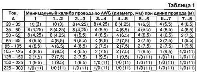


 Leave your comment on this article: