|
|


 Arabic
 Bengali
 Chinese
 English
 French
 German
 Hebrew
 Hindi
Hindi Italian
 Japanese
 Korean
 Malay
Malay Polish
 Portuguese
 Spanish
 Turkish
 Ukrainian
 Vietnamese
|
ENCYCLOPEDIA OF RADIO ELECTRONICS AND ELECTRICAL ENGINEERING UMZCH with adjustable output impedance. Encyclopedia of radio electronics and electrical engineering
Encyclopedia of radio electronics and electrical engineering / Transistor power amplifiers I am more and more convinced from my own amateur radio experience of the correctness of the provisions of article [1] on the dependence of the nature of the sound ("tube" or "transistor") on the operation of the UMZCH - loudspeaker system. The sound features of the speakers are not at all connected with the element base of the UMZCH and not with the presence or absence of an OOS, but to a large extent with its (UMZCH) output impedance, so I will share the results of my research. After many experiments with transistor UMZCH (with various feedback [2] and without it at all), each time comparing the sound with the "standard" in the form of UMZCH tube radio "VEF-Radio" (single-cycle, pentode, with ultra-linear switching on of the lamp and a shallow common OOS), I came to the following conclusion. The generally accepted opinion that a low (preferably "zero" or even negative) output impedance of the UMZCH is favorable for reproducing low frequencies is not always true. If the output impedance of the UMZCH is approximately 20 ... 50% of the loudspeaker impedance (at the same time, there is no need to talk about deep damping), the soft sound of the double bass in jazz is more pleasant (of course, purely subjective). On the other hand, when listening to rock, modern electronic music with "assertive" bass, stronger speaker damping is required. A funny situation arises when it is desirable for each style of music to have its own UMZCH: for jazz, it is better to have a tube one and without a common OOS, for rock, a transistor with a deep voltage OOS (OOSN), which provides a low output impedance. In this regard, I propose a device tested on a mock-up that "reconciles" this contradiction. The adjustable output impedance of the UMZCH allows you to smoothly turn the transistor amplifier into a "tube triode" or "pentode" amplifier without OOS, but without the third harmonic coefficient characteristically high for pentodes. This transformation of the UMZCH is possible with the help of variable resistors, which translate the OOS by voltage into the OOS by current through the load with a constant transfer coefficient of the device. The UMZCH layout diagram is shown in fig. one.
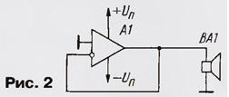
The output resistance is adjusted as follows: in the lower extreme position of the engines of the dual variable resistors R4.1, R4.2, only OOSN occurs, the depth of which is determined by the ratio of resistors R3, R1 and the initial gain DA1 without NF. In the other extreme position of the sliders, variable resistors create only current OOS (OOS). In this case, depending on the load resistance (4 or 8 ohms), switch SA1 is closed or opened, which changes the resistance of the current sensor (R5, R6). When moving the sliders of variable resistors, the overall gain of the device, relatively speaking, does not change. Conditionally, since the voltage transfer coefficient in the OOST mode is related to the frequency dependence of the loudspeaker impedance. Only the output resistance of the UMZCH changes from close to zero to several tens of kilo-ohms. Its desired value is set by ear according to the subjectively more pleasant sound of a musical work of the corresponding style. Dual variable resistors R4 must be of group A (with a linear control characteristic). Instead of variable resistors, you can use any switch for two directions and 11 positions with a chain of 680 Ohm resistors (2x10 pcs.). True, in this case, in order to prevent sharp clicks and possible failure of the loudspeaker when the output impedance of the UMZCH changes, it is necessary to turn off the UMZCH power each time, which reduces efficiency when selecting the desired sound character. If desired, you can change the UMZCH gain, but the following relationships must be met: Ku \u3d R1 / R2 \u1d Rn / RdxRXNUMX / RXNUMX; Rн/Rд=10; R2 = 5R4. Here, Rн is understood as the passport value of the resistance of the loudspeaker at a frequency of 1000 Hz; Rd is the resistance of the current sensor. And one more thing: variable depth feedback is a subtle and capricious "thing", and the combination of different types of OOS is even more so. Therefore, before using any other UMZCH in the circuit under consideration (analogues of MDA2020 are TDA2020, K174UN11 [3]), it is desirable to achieve stability (no self-excitation) by selecting correction circuits when the amplifier is turned on according to the repeater circuit (Fig. 2). Here A1 is UMZCH without a chain of general environmental protection.
The main disadvantage of the circuit in Fig. 1 is the presence of mechanical contacts in the feedback circuit (resistors R4 or a switch replacing them). In addition, the resistance of the current sensor (Rd) limits the maximum value of the damping factor even with a "zero" output resistance of the UMZCH. As an UMZCH, it is advisable to choose a microcircuit with a low intrinsic harmonic coefficient without negative feedback. The power and type of resistors R5, R6, as well as their resistance can be changed within certain limits depending on the output power of the UMZCH, the given gain and the input resistance of the UMZCH. Such an amplifier can be successfully used to study the properties of electrodynamic heads in the entire operating frequency range at various impedances. For example, some heads are not very sensitive to the output impedance of the amplifier, others are more sensitive (high intermodulation distortion at mid frequencies). The proposed structure of the feedback controller requires dual variable resistors. It is possible, however, to simplify this circuit by "transforming" the UMZCH feedback with a single variable resistor, as shown in Fig. 3.
The result is the same: in the left position of the engine, the output resistance of the UMZCH is minimal, in the right position it is maximum. In relation to the loudspeaker, the minimum output impedance of the signal source is limited by the resistance of the current sensor included in the load circuit and is about a tenth of the load resistance. For damping most loudspeakers, this ratio is sufficient. To increase the stability of the UMZCH, it is not at all necessary to correct its frequency response for a "single" gain. We recommend using the recommendations contained in the article A Syritso "Features of UMZCH with high output impedance", published in Radio, 2002, No. 2, pp. 16, 17. Literature
Author: A.Maslov, Zhukovsky, Moscow Region
Machine for thinning flowers in gardens
02.05.2024 Advanced Infrared Microscope
02.05.2024 Air trap for insects
01.05.2024
▪ Wireless control of any battery powered devices ▪ Mosquitoes weaned from drinking blood ▪ Come in, you'll be sniffed here ▪ Legumes force bacteria into symbiosis
▪ section of the site Car. Article selection ▪ article Joseph the Beautiful (Chasest Joseph). Popular expression ▪ article In which major city do seawater fill most of the toilets? Detailed answer ▪ article Electrician in the house. Directory ▪ article Putty for joining metal with glass. Simple recipes and tips ▪ article Cards with numbers. Focus Secret
Home page | Library | Articles | Website map | Site Reviews
www.diagram.com.ua |


 Leave your comment on this article: