Audio cassette player amplifier. Encyclopedia of radio electronics and electrical engineering

Encyclopedia of radio electronics and electrical engineering / Transistor power amplifiers
 Comments on the article
This amplifier can be used in the modernization of car radios, as well as simple stationary or portable tape players. It features low self-noise and electronic tone control.
The player's amplifier is designed to play audio tracks from compact cassettes through external speakers and can be used to upgrade car radios.
The advantages of the described amplifier include a low level of intrinsic noise, a sufficiently large output power and a depth of tone and balance control. It differs from similar devices in ease of setup, small dimensions, high sound quality.
The device (its schematic diagram is shown in Fig. 1) contains a two-channel playback amplifier on a DA1 K157UL1A chip in an unusual switching circuit - it is described in detail in [1]. The reduced output voltage of the SW (about 30 mV) necessitated an additional linear amplifier assembled on the DA3 K548UN1A microcircuit [2]. The signals amplified by it are fed to the integrated tone and balance control DA2 TDA1524 [3] and then through the volume control to the power amplifier, which is the DA4 TDA1557 chip [3].
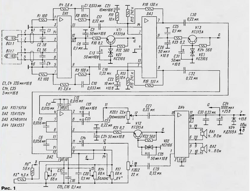
(click to enlarge)
The playback volume could be adjusted by electronic control of the TDA1524 chip and without a dual variable resistor, but in this case noise is heard in the speakers even at minimum volume. All microcircuits used, except for DA4, are supplemented with supply voltage stabilizers.
Main Specifications
- Output power, Рout, W, for RH= 4 Ohm......2x20
- for RH= 8 Ohm......2x10
- Depth of balance adjustment, dB......38
- Tone control, dB, at LF (40Hz)......-20...+18
- RF(16kHz)......±16
- Frequency response range, Hz, for IEC-I tape......31,5...14000
- IEC-II......31,5...18000
- Relative noise level, dB......-65
- Consumption current, A, at Upit = 12... 18 V. no more......5
The device is assembled on a printed circuit board made of one-sided foil fiberglass with dimensions of 145x20 mm, which allows it to be placed in most cases of industrial car radios. The heat sink for the TDA1557 chip is an aluminum plate with an area of 200 ... 400 cm2, depending on the specific case design.
The player's amplifier uses foreign-made oxide capacitors due to their smaller dimensions. Capacitors C17, C18, C27, C29, C30, C32 - K73-9 or K73-17, all others (non-polar) - KM-5 or similar. In the amplifier, you can use transistors of the KT315 series with any letter index (VT1-VT3), KS210B zener diodes (VD1-VD3). You can also use D814V by connecting them with an anode to a common wire. Diode VD4 from the KD209 or KD208 series with any letter index.
All resistors, except for variables, MLT-0,125 W (or 0,25 W). Variable resistors R7, R14, R17 - any type with a linear adjustment characteristic; R20 - double, with exponential control characteristic (option B).
It is advisable to use AC loudspeakers with a resistance of 4 ... 8 ohms and a power of 20 ... 30 watts.
For the experiment in the assembled structure, the author tried to install various magnetic heads [1], and in most cases good results were obtained.
A drawing of a printed circuit board and a layout of parts are shown in fig. 2. Resistors R1, R2, R4, R5, R24 are installed perpendicular to the printed circuit board, and resistor R6 is placed above the DA2 chip.
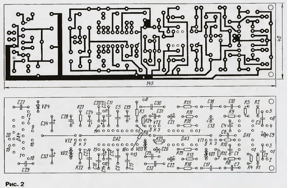
(click to enlarge)
It is advisable to use power wires with a cross section of at least 0,5 mm2. It is advisable to bring them out with a twisted pair. The negative wire is soldered to the contact pad 8 of the board, and from it to the case and other components of the device. All wires to the volume control must be shielded. The wires connecting the balance and tone controls with the board can not be shielded.
The wires connecting the magnetic head to the board carefully shield two wires of each channel in their screen, the screens are connected on contact pads 1, 6 only from the side of the board. The screens must be insulated from the outside, the wire sections to the magnetic head leads outside the screen should be made as short as possible.
Establishing a properly assembled device comes down to tuning to the required frequency of the resonant circuits formed by the head sections BG1 and capacitors C2 and C3. In some cases, to correct the range of tone control, you need to select the resistance of resistors R3, R6 and check the operation of voltage regulators for DA1-DA3.
When using the device in a stationary audio cassette player, it is supplemented with a 15 V mains power supply, rated for current up to 5 A with a low ripple level (possibly stabilized).
Literature
- Shikhatov A. Playback amplifier on the K157UL1A chip. - Radio, 1994, No. 4. p. 14.
- Ataev D. I., Bolotnikov V. A. Analog integrated circuits. - M.: Radio and communication, 1991, p. 68.
- Microcircuits for audio and radio equipment. Encyclopedia of Repair, vol. 3. - M.: DODEKA, p. 214, p. 220.
Author: O. Shcherbich, Vladikavkaz, North Ossetia
 See other articles Section Transistor power amplifiers.
Read and write useful comments on this article.
<< Back
 Latest news of science and technology, new electronics:
Machine for thinning flowers in gardens
02.05.2024
In modern agriculture, technological progress is developing aimed at increasing the efficiency of plant care processes. The innovative Florix flower thinning machine was presented in Italy, designed to optimize the harvesting stage. This tool is equipped with mobile arms, allowing it to be easily adapted to the needs of the garden. The operator can adjust the speed of the thin wires by controlling them from the tractor cab using a joystick. This approach significantly increases the efficiency of the flower thinning process, providing the possibility of individual adjustment to the specific conditions of the garden, as well as the variety and type of fruit grown in it. After testing the Florix machine for two years on various types of fruit, the results were very encouraging. Farmers such as Filiberto Montanari, who has used a Florix machine for several years, have reported a significant reduction in the time and labor required to thin flowers.
... >>
Advanced Infrared Microscope
02.05.2024
Microscopes play an important role in scientific research, allowing scientists to delve into structures and processes invisible to the eye. However, various microscopy methods have their limitations, and among them was the limitation of resolution when using the infrared range. But the latest achievements of Japanese researchers from the University of Tokyo open up new prospects for studying the microworld. Scientists from the University of Tokyo have unveiled a new microscope that will revolutionize the capabilities of infrared microscopy. This advanced instrument allows you to see the internal structures of living bacteria with amazing clarity on the nanometer scale. Typically, mid-infrared microscopes are limited by low resolution, but the latest development from Japanese researchers overcomes these limitations. According to scientists, the developed microscope allows creating images with a resolution of up to 120 nanometers, which is 30 times higher than the resolution of traditional microscopes. ... >>
Air trap for insects
01.05.2024
Agriculture is one of the key sectors of the economy, and pest control is an integral part of this process. A team of scientists from the Indian Council of Agricultural Research-Central Potato Research Institute (ICAR-CPRI), Shimla, has come up with an innovative solution to this problem - a wind-powered insect air trap. This device addresses the shortcomings of traditional pest control methods by providing real-time insect population data. The trap is powered entirely by wind energy, making it an environmentally friendly solution that requires no power. Its unique design allows monitoring of both harmful and beneficial insects, providing a complete overview of the population in any agricultural area. “By assessing target pests at the right time, we can take necessary measures to control both pests and diseases,” says Kapil ... >>
| Random news from the Archive What do whales sing
18.04.2018
The songs of bowhead whales are similar to jazz, oceanographers at the University of Washington came to this conclusion. For three years, scientists have collected 184 whale songs from the Svalbard population.
Bowhead, or polar, whales live in the polar latitudes of the Northern Hemisphere. They can reach 18 meters in length and weigh up to 100 tons, and live longer than 100 years.
Bowhead whales do not migrate south like other whales, but live year round in zooplankton-rich Arctic waters. Polar whales move more often alone or in small groups, while their vocal repertoire is very rich. With the help of their songs, they communicate during feeding and movement. In addition, male polar whales sing long complex songs, especially during the breeding season, from November to March.
Bowhead whales are one of the few mammals that sing songs. They give out a series of sounds with variable frequency and amplitude, which are combined into a kind of scale, lasting at least several minutes and repeating for hours or days.
Among cetaceans, humpback whales also sing songs. Their songs are distinguished by a hierarchical structure and are built from sound units to a scale, and from them to structured themes. Over the years, their structure changes, and sometimes the whales update their repertoire. Each population has its own songs, but different populations exchange them with each other.
The songs of bowhead whales have been studied much worse. The peak of their vocal activity fell on the darkest and coldest time of the year.
|
Other interesting news:
▪ Dust-resistant, waterproof lenses Canon Dust Donuts
▪ There may be more than a hundred planets in the solar system
▪ mobile phone fast charging technology
▪ Self-winding earpiece
▪ wool house
News feed of science and technology, new electronics
 Interesting materials of the Free Technical Library:
▪ section of the site Big encyclopedia for children and adults. Selection of articles
▪ article by Yang Zhu. Famous aphorisms
▪ article Whose notes can be read both from top to bottom and from bottom to top, forming a duet of two violins? Detailed answer
▪ Chayote article. Legends, cultivation, methods of application
▪ article Auto 400. Car amplifier based on the STK4048XI chip. Encyclopedia of radio electronics and electrical engineering
▪ article Cell phone charger repair. Encyclopedia of radio electronics and electrical engineering
Leave your comment on this article:
 All languages of this page
Home page | Library | Articles | Website map | Site Reviews

www.diagram.com.ua
2000-2024


 Arabic
 Bengali
 Chinese
 English
 French
 German
 Hebrew
 Hindi
Hindi Italian
 Japanese
 Korean
 Malay
Malay Polish
 Portuguese
 Spanish
 Turkish
 Ukrainian
 Vietnamese
