|
|
ENCYCLOPEDIA OF RADIO ELECTRONICS AND ELECTRICAL ENGINEERING Frequency synthesizer. Encyclopedia of radio electronics and electrical engineering
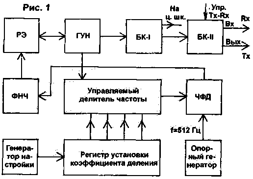
Encyclopedia of radio electronics and electrical engineering / Frequency synthesizers Recently, the requirements for the frequency stability of the local oscillators of transceivers have increased, especially in digital communication, RTTY, etc. A number of publications have appeared describing frequency synthesizers. Basically, these are complex devices, sometimes with the use of programmable imported microcircuits. Often, these devices are bulky, consume high current, and interfere with the transceiver's receive path. Details are usually scarce. The author designed and built a simple synthesizer from widely available parts; at the same time, its parameters (first of all, frequency stability) are not inferior to complex synthesizers on imported microcircuits, and simplicity and clarity can serve as a good tool for studying such devices by many radio amateurs. The block diagram of the frequency synthesizer is shown in Fig.1. The synthesizer has a voltage-controlled local oscillator (VCO), the average frequency of which, depending on the range, is set by a switch. A reactive element (RE) is included in the VCO circuit - a varicap. The VCO frequency voltage is applied to the controlled frequency divider, the division factor of which is set from the division factor setting register. The state of this register (number) is set by the tuning generator. The VCO signal after the divider is fed to a frequency-phase detector (FPD), where it is compared in frequency with the frequency of the reference oscillator (in this embodiment, 512 Hz). With PFD, the frequency setting error signal is fed through a low-pass filter (LPF) to a reactive element (RE).
In this way, the frequency of the VCO is adjusted. The signal from the VCO is fed to the first buffer stage (BC-1), in which the VCO frequency is either divided by 2, or simply goes to the BC-1 output without division (depending on the range and the required local oscillator frequency). The second buffer stage (BK-11) simply switches the voltage of the required local oscillator frequency to either the receive mixer (RX) or the transmit mixer (TX). As can be seen from the circuit diagram (Fig. 2), the VCO is made on the transistor VT1. Its circuit includes a VD1 varicap. Switching the middle frequency of the VCO is carried out by the switch S1-1, which, in parallel with the main inductance (L8), connects additional ones (L1 ... L7) or C2. Through the emitter followers VT2, VT3, the signal is fed to the first buffer stage (DD1). The division factor of the K1533TM2 chip is set (depending on the range) by switch S1-3. S1-2 toggles the digital IF frequency preset, depending on whether the local oscillator frequency is higher or lower than the transceiver's operating frequency. In the author's transceiver, the intermediate frequency is 8 MHz, and the local oscillator frequencies on various bands are given in Table 1.
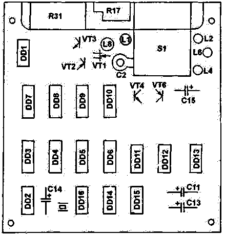
S1-4 performs electronic band switching (bandpass filters) in the transceiver paths. The controlled frequency divider is made on the elements DD7...DD10. These are K1533IE7 microcircuits. As can be seen from the diagram, the signal from VT3 is applied to pin 4 of DD7. When the count reaches zero in all digits, the signal from pin 13 DD10 will set all the elements of the divider to the state specified from the register at the inputs "D" of the DD7 ... DD10 microcircuits. After that, there will be an account for "reducing" to the zero state again. Thus, the frequency division is carried out in accordance with the value set at the inputs "D". The value of the division coefficient is set in the register DD3 ... DD6 by a tuning generator assembled on a DD13 and DD12.4 chip. The generator is controlled by the potentiometer R31. If its movable element is in the middle position, the generator does not work. If you move it up, generation will begin on the lower three elements according to the scheme DD13. In this case, from output 10 DD13, the signal will go to input +1 (pin 5), DD3 and the register will start stepwise switching to increase the number written in it, which means that the divider frequency division factor will begin to increase, and the auto-tuning system will increase the frequency of the VCO with each pulse by 512 Hz. The frequency of the tuning generator pulses (tuning frequency) depends on the extent to which we move R31 "up" in this case, and can vary from 0,5 Hz (slow step tuning) to 1000 Hz - fast tuning. That is, the more the potentiometer R31 is moved up, the faster the restructuring. To reduce the frequency, the potentiometer R31 slider is moved down; the generator will start working on the top three elements DD13, and the register will "go to decrease". This is how the setting is done. This is an unconventional way, but you can quickly get used to it. The reference frequency generator is made on microcircuits DD14...DD16. A crystal oscillator is made on DD16. Quartz is used from electronic clocks. To adjust the quartz frequency, and hence the local oscillator frequency within the "grid step", the method of changing the supply voltage to DD16 using the R15 ... R17 chain is used. In this case, a smooth tuning of the VCO by 1 kHz is achieved. The frequency of the crystal oscillator is divided by 64 using microcircuits DD14, DD15 and is fed to one of the inputs of the PFD, made on DD11, DD12. Voltage is also supplied there from the output of the controlled frequency divider. The error signal from the PFD output through the low-pass filter (R1, R2, R26, C1, C3, C9) is fed to the varicap. The R27, C15 chain stabilizes the operating mode when switching the frequency, and eliminates the "croak and chirp" characteristic of systems with a similar PFD during tuning. The chain R18, C14 is used to initially set the register to state 32768 (when the transceiver is turned on). BK-I - a simple signal switch on logic elements. The synthesizer is made as a single block on a board with dimensions of 125x120 mm. Adjustment elements S1, R17, R31 are attached to the board using an aluminum corner. Inductors are not critical to the parameters, and any diameter of 6 ... 7 mm can be used, tuning - with brass cores. Potentiometer R31 - type SP-1. Switch S1 - type PG3-11P4N, compact. It is desirable to use microcircuits of the 1533 series, although it is also possible to use the 155 series, but in this case the current consumption will increase from 350 to 550 mA for a +5 V source. The current consumption for voltage is 12V - 25 mA. The author used a board with a single-sided printed wiring (Fig. 3), so there are a lot of wire jumpers on the side with the details. You can pay in other ways as well.
The author performed a 512 Hz generator on DD14 ... DD16 microcircuits and watch quartz. You can use other options with other quartz, but the output frequency should be in the range of 400 ... 650 Hz. The setup is as follows: 1. Check the operation of the setup generator. In the middle position of R31 (a sector of approximately -45 °), generation should be absent; if it exists, or the sector of lack of generation is small or large, this is eliminated by the selection of R29, R30. At the extreme positions of R31, the generation frequency should be about 1 kHz. 2. The operation of both the quartz oscillator itself and its dividers is checked. The frequency at the output of DD15 (pin 8) should be 512 Hz (when using clock quartz). 3. Next, tune the VCO. To do this, the right (according to the circuit diagram) output R1 is unsoldered from the board, and a voltage of +5 V is applied to it from a voltage divider (you can use a 30 ... 6,5 kΩ potentiometer). The range of 20 m is switched on. the required value of the frequency fhet.av (according to Table 8); then turn on the range of 1 m and set fhet.av. using core L160. We turn on the range of 30 m and, selecting the turns L3, we adjust fhet.av (L3, L5, L7 are wound on cores with a diameter of 3 mm and mounted directly on S1). We turn on the range of 80 m and use C2 to set fhet.av. We turn on the range of 14 m and use the L4 core to set fhet.av. The 10 m range is divided into two separate sub-bands: I - 28,00 ... 28,8 MHz and II - 28,8 ... 29,7 MHz. We turn on the second subrange of 10 m and use the L6 core to set it to fhet.av. Next, we turn on the first subrange of 10 m and, by selecting turns L7, we adjust its fhet.av. In our case, it is approximately equal to fhet.sr for the range of 18 m. We turn on the range of 12 m and, by selecting turns L5, we set it to fhet.av. Of course, you can use this synthesizer circuit for a transceiver with a different intermediate frequency, and not 8 MHz. Then, first you need to recalculate Table 1 for a different intermediate frequency, and then make some changes in the VCO range switching scheme. 4. A comprehensive check of the synthesizer is performed - any range is turned on (before that, it is necessary to solder R1 into the circuit) and the operating frequency of the local oscillator (or transceiver on a digital scale) is determined. If it is more or less than the frequency of the range - by turning it all the way to the corresponding side of R31, we first set it within the range, and then by turning R31 at a small angle from the middle (smooth tuning) we set the desired frequency. This checks the operation of the transceiver on all ranges. The restructuring time from range to range with some skill is no more than 10 s. If during the setup process some operations deviate from the norm, it means that there are either installation errors or faulty parts. In general, the synthesizer proved to be reliable, exceptionally stable, not interfering with other circuits and transceiver paths. Unfortunately, only experienced radio amateurs familiar with digital technology can repeat the scheme. In general, the description may be of interest from the point of view of some "KNOW-HOW", in particular, the use of the original circuit on 1533TM2 (DD1), which, depending on the voltages applied to the "R" inputs, divides by 2 or simply broadcasts the signal; tuning generator circuits, etc. Literature 1. Shilo V.L. Popular digital circuits. - 1988.
Author: L. Rivaenkov (UA3LDW), Smolensk; Publication: N. Bolshakov, rf.atnn.ru
Artificial leather for touch emulation
15.04.2024 Petgugu Global cat litter
15.04.2024 The attractiveness of caring men
14.04.2024
▪ You need to quit smoking fast ▪ Tarsiers communicate on ultrasound
▪ section of the site Electricity for beginners. Article selection ▪ Figaro article here, Figaro there. Popular expression ▪ article Who did the ancient Greeks consider the progenitors of modern mankind? Detailed answer ▪ article Where does electricity come from? Directory ▪ article Mordant for imitation of rosewood. Simple recipes and tips
Home page | Library | Articles | Website map | Site Reviews www.diagram.com.ua |


 Arabic
 Bengali
 Chinese
 English
 French
 German
 Hebrew
 Hindi
Hindi Italian
 Japanese
 Korean
 Malay
Malay Polish
 Portuguese
 Spanish
 Turkish
 Ukrainian
 Vietnamese


 Leave your comment on this article: