|
|


 Arabic
 Bengali
 Chinese
 English
 French
 German
 Hebrew
 Hindi
Hindi Italian
 Japanese
 Korean
 Malay
Malay Polish
 Portuguese
 Spanish
 Turkish
 Ukrainian
 Vietnamese
|
ENCYCLOPEDIA OF RADIO ELECTRONICS AND ELECTRICAL ENGINEERING Active probe for oscilloscope. Encyclopedia of radio electronics and electrical engineering
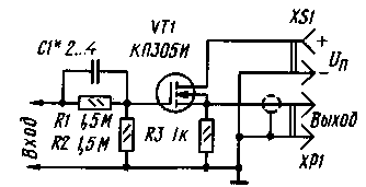
Encyclopedia of radio electronics and electrical engineering / Measuring technology The input capacitance of modern oscilloscopes is about 30...50 pF. When measuring, the capacitance of the connecting cable is added to it, and the total input capacitance reaches 100 ... 150 pF. This can lead to a significant distortion of the measurement results and incorrect settings, for example, notch filters of the output stages of tape recorder recording amplifiers. That is why, when conducting research in circuits that are critical to the introduced capacitance of the measuring device, it is necessary to use special matching devices that have a large input resistance and a small capacitance. For most practical work, two main types of devices are needed: for low-amplitude harmonic signals (1 ... 50 mV) with a transmission coefficient K> 1 and for high-amplitude signals (up to 10 ... having a transmission coefficient K=20...0,2. The widespread use in recent years of high-speed analog and digital microcircuits operating at relatively high voltages (op-amps for wide use, microcircuits of the K561 series - up to 15 V) has revealed the need for a device operating in a wide voltage range with the ability to transmit a constant signal component.
A diagram of such a device in the form of a probe is shown in Fig. 1. It is made according to the classical source follower circuit using a MOS transistor and contains a minimum number of parts. The operating frequency range is O...5 MHz. Power is supplied from any current source with a voltage of 7 ... 15 V, for example, a 7D-0,115-U1.1 storage battery or Krona, Korund galvanic batteries. The input capacitance of the probe is not more than 4 pF, the input resistance is not less than 3 MΩ. The output voltage at Uin=0 is 2,5 V. The range of input voltages in the area of negative values (before cutoff) is 7 V, in the area of positive values (before the start of limitation) is 13 V at Upit=9V and 26V at Upit=15V. The transmission coefficient in the specified frequency range is 0,4. Resistors R1 and R2 form the input voltage divider, capacitor C1 is used for frequency compensation. Due to the significant variation in the parameters of specific transistors, the characteristics of probe designs can also differ mainly in cutoff voltage and transfer coefficient. To obtain the maximum operating range in the region of negative input voltages, it is necessary to use transistors with the maximum (in absolute value) cutoff voltage. The author used a transistor with Uzi otc = 4,2 V. Most KP305I transistors have a lower value of Uzi ots, therefore, if necessary, the probe cutoff voltage can be increased by reducing the input divider gain, for example, by increasing the resistance of the resistor R1. However, for many measurements that require adjustment to the maximum or minimum voltage, the cutoff voltage value of the probe is not significant, since the adjustment can be made on the positive half-wave of the signal. The probe is assembled in a case from a felt-tip pen. The installation is volumetric, without the use of additional structural elements. The conclusions of the radio elements are connected directly to each other. The probe is connected to the oscilloscope with a shielded cable no longer than 30 cm. The design used resistors type MLT-0,125. Capacitor C1 is constructive, it is made with a PEV wire with a diameter of 0,15 ... 0,35 mm. The wire must be soldered to the left (according to the diagram) terminal of the resistor R1 and wound 12 turns on the right terminal. The capacitance is selected by changing the number of turns. At the end of the tuning on the capacitor thus obtained, clean the track with a fine-grained sandpaper, tin it and solder it in a thin layer (to eliminate parasitic inductance). When mounting the probe, measures should be taken to prevent the breakdown of the field-effect transistor by static electricity and interference from the network. Setting up the device consists in calibrating to obtain the required transfer coefficient and selecting the capacitance of capacitor C1. Calibration will require the use of a regulated DC power supply and a voltmeter. By selecting the resistance of the resistor R1, the transfer coefficient is set to K = 0,4 (or 0,5), while taking into account the initial bias voltage at the output. When selecting the capacitance of the capacitor C1, a rectangular pulse generator with an output signal amplitude of 2 ... 10 V and a repetition rate of 1 ... 10 kHz is required. To provide steep fronts, you can use a trigger frequency divider, for example, on microcircuits of the K155, K176, K561 series. By changing the capacitance of the frequency compensation capacitor C1, rectangular pulses are obtained on the oscilloscope screen without a blockage of the fronts, the amplitude of the surges at the fronts should be no more than 10% of the pulse amplitude. Too much capacitance causes significant surges along the fronts, insufficient - their tightening. On the body of the manufactured structure, it is necessary to put inscriptions of the device parameters - input capacitance, resistance and transfer coefficient. When making measurements with a readout of the DC component, the oscilloscope must be corrected for the readout level. To do this, close the probe input and set the oscilloscope beam to zero. Author: A. Grishin, Moscow; Publication: N. Bolshakov, rf.atnn.ru
The world's tallest astronomical observatory opened
04.05.2024 Controlling objects using air currents
04.05.2024 Purebred dogs get sick no more often than purebred dogs
03.05.2024
▪ Neurons evaluate the benefit of a habit ▪ Intel retires Direct Rambus DRAM (DR DRAM) ▪ Chemists fight global warming
▪ section of the site Medicine. Selection of articles ▪ article Frog-traveler. Popular expression ▪ article What is the function of the ears in addition to hearing? Detailed answer ▪ article Anti-terrorism security and protection of children. Standard instruction on labor protection ▪ article Focus with a folding box. Focus Secret
Home page | Library | Articles | Website map | Site Reviews
www.diagram.com.ua |

 Leave your comment on this article: