Electroshock protection. Encyclopedia of radio electronics and electrical engineering

Encyclopedia of radio electronics and electrical engineering / Security and safety. Personal safety
 Comments on the article
I want to bring to your attention an electroshock means of self-defense. The product is very effective, including psychologically.
The basis of the device is a DC voltage converter (Fig. 1). At the output of the device, I used a multiplier on KTs-106 diodes and 220 pF x 10 V capacitors. 10 D-0,55 batteries are used as power. With smaller ones, the result is slightly worse. Batteries "Krona" or "Korund" can also be used. It is important to have 9-12 volts. Batteries are convenient only because they can be charged.

Ris.1
A very important element is the transformer, which I made from a ferrite core (a ferrite rod from a radio receiver with a diameter of 8 mm), but a ferrite transformer from TVS worked more efficiently - I made a bar from a "P"-shaped one.
I took the rules for winding a high-voltage winding from the Radio magazine for 1992 ("Electric Match") - I laid insulation through every thousand turns. For inter-turn insulation, I used FUM tape (fluoroplat). In my opinion, other materials are less reliable. Experimenting, I tried electrical tape, mica, used PEL-SHO wire. The transformer did not serve long - the windings were "flashed".
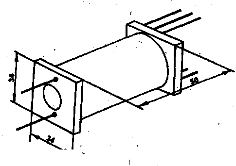
The case was made from a plastic box of suitable sizes - plastic packaging from an electric soldering iron. Original dimensions: 190 x 50 x 40 mm (see photo). In the case, I made plastic partitions between the transformer and the multiplier, as well as between the electrodes on the soldering side - precautions to avoid the passage of a spark inside the circuit (case), which also protects the transformer.
From the outer part, under the electrodes, I placed small "antennae" made of brass to reduce the distance between the electrodes - a discharge is formed between them. In my design, the distance between the electrodes is 30 mm, and the length of the crown is 20 mm. A spark is also formed without a "mustache" - between the electrodes, but there is a danger of breakdown of the transformer, its formation inside the case. I spied the idea of "mustache" on "branded" models.

Fig.2 (click to enlarge)
In order to avoid self-switching when worn, it is more advisable to use a slide-type switch.
I want to warn radio amateurs about the need for careful handling of the product both during the design and commissioning period, and with the finished device. Remember that it is directed against a bully, a criminal, but, at the same time, against a person. Exceeding the limits of necessary defense is punishable by law.
Author: A.Vorobiev, Kursk
Refinement of electroshock protective equipment
I want to propose a winding technology for a high-voltage transformer for an electric shock circuit from A. Vorobyov's article [1].
The frame is made of a 50 mm felt-tip pen, which accurately fits a ferrite core with a diameter of 8 mm. Cheeks measuring 40 x 40 mm are cut out of ordinary plastic and glued with dichloroethane. For insulation, instead of a scarce fluoroplastic, interelectrode insulation from a capacitor from a fluorescent lamp 4 μF x 300 V 0,035 mm thick was used, which I pre-cut exactly to the width of the frame. When powered by Krona, the high-voltage winding contains 10 turns of PEV-000 wire with a diameter of 2 mm. After winding every three layers, I smeared the winding with a wide brush with epoxy resin, slightly diluted with acetone, so that the resin was not very viscous, and laid the insulation in 0,15 layers. Further, without waiting for hardening, he continued winding. Between the high-voltage and other windings there is insulation - 2 layers with epoxy. The finished transformer is wrapped with one layer of fiberglass and filled with resin. The conclusions of the high-voltage winding must be brought out through the holes in the cheeks at the beginning and end of the winding. When working for 6 minutes with the maximum divorced contacts, the transformer did not break through.
I replaced the KT818 transistors with KT816 with any letter and small plate heatsinks, which reduced the weight and size of the device. Diodes KTs106 - preferably with the letters B, G. The size of the case when powered by the "Krona" without taking into account the "whiskers" is -135 x 58 x 36 mm. Weight - about 300 grams.
Literature
1. A. Vorobyov. Electroshock protection. Radio amateur. - 1994. - No. 3. - P.46.
Author: A. Antsiferov, Moscow; Publication: N. Bolshakov, rf.atnn.ru
 See other articles Section Security and safety. Personal safety.
Read and write useful comments on this article.
<< Back
 Latest news of science and technology, new electronics:
Artificial leather for touch emulation
15.04.2024
In a modern technology world where distance is becoming increasingly commonplace, maintaining connection and a sense of closeness is important. Recent developments in artificial skin by German scientists from Saarland University represent a new era in virtual interactions. German researchers from Saarland University have developed ultra-thin films that can transmit the sensation of touch over a distance. This cutting-edge technology provides new opportunities for virtual communication, especially for those who find themselves far from their loved ones. The ultra-thin films developed by the researchers, just 50 micrometers thick, can be integrated into textiles and worn like a second skin. These films act as sensors that recognize tactile signals from mom or dad, and as actuators that transmit these movements to the baby. Parents' touch to the fabric activates sensors that react to pressure and deform the ultra-thin film. This ... >>
Petgugu Global cat litter
15.04.2024
Taking care of pets can often be a challenge, especially when it comes to keeping your home clean. A new interesting solution from the Petgugu Global startup has been presented, which will make life easier for cat owners and help them keep their home perfectly clean and tidy. Startup Petgugu Global has unveiled a unique cat toilet that can automatically flush feces, keeping your home clean and fresh. This innovative device is equipped with various smart sensors that monitor your pet's toilet activity and activate to automatically clean after use. The device connects to the sewer system and ensures efficient waste removal without the need for intervention from the owner. Additionally, the toilet has a large flushable storage capacity, making it ideal for multi-cat households. The Petgugu cat litter bowl is designed for use with water-soluble litters and offers a range of additional ... >>
The attractiveness of caring men
14.04.2024
The stereotype that women prefer "bad boys" has long been widespread. However, recent research conducted by British scientists from Monash University offers a new perspective on this issue. They looked at how women responded to men's emotional responsibility and willingness to help others. The study's findings could change our understanding of what makes men attractive to women. A study conducted by scientists from Monash University leads to new findings about men's attractiveness to women. In the experiment, women were shown photographs of men with brief stories about their behavior in various situations, including their reaction to an encounter with a homeless person. Some of the men ignored the homeless man, while others helped him, such as buying him food. A study found that men who showed empathy and kindness were more attractive to women compared to men who showed empathy and kindness. ... >>
| Random news from the Archive The secret of chewing chocolate
24.01.2023
A team of scientists from the University of Leeds focused not on the taste of chocolate, but on the tactile sensations associated with eating it. The analysis was performed using a premium brand of dark chocolate on a 3D artificial tongue-like surface.
The scientists applied the analytical methods of tribology, one of the branches of engineering that studies the interaction of surfaces and liquids, the level of friction between them and the role of lubrication: in this case, saliva or fat from chocolate.
"Tribology provides a mechanistic understanding of how food feels in the mouth. This knowledge can be used to develop products that taste better, have better texture or are healthier," explains Anvesha Sarkar, professor at the School of Food Science and Dietetics in Leeds.
When chocolate hits the tongue, it releases a fatty film that coats the tongue and other surfaces in the mouth. It is through it that we feel chocolate as something smooth and pleasant.
After that, the cocoa solids are released and become more important in terms of tactile sensations, so the fat loses its value and its amount can be reduced without affecting the texture of the product.
"Contains chocolate 5% or 50% fat - it doesn't really matter, it will still form drops in the mouth, which create the same pleasant sensation," said Anvesha Sarkar.
According to Siavash Soltanahmadi of the Leeds School of Food Science and Dietetics and leader of the study, this work could help develop reduced-fat chocolate without changing its texture.
"By understanding the physical mechanisms that occur when eating chocolate, it is possible to develop a next generation product that feels and tastes like high-fat chocolate, but is more beneficial," Soltanahmadi explained.
The researchers believe that the new knowledge can be applied to the study of other foods that are subject to a phase transition, when a substance changes from a solid to a liquid, such as ice cream, margarine or cheese.
|
Other interesting news:
▪ Soldier boots as a source of electricity
▪ SPARC T5 servers powered by the world's fastest microprocessors
▪ How to recognize fake lycra
▪ Camera Interface Development Kit
▪ Artificial tungsten sheet
News feed of science and technology, new electronics
 Interesting materials of the Free Technical Library:
▪ section of the site Radio - for beginners. Article selection
▪ article by Helen Rowland. Famous aphorisms
▪ article What do molluscs eat? Detailed answer
▪ article Burns. Health care
▪ article Turn counter for winding a transformer using a computer LPT port. Encyclopedia of radio electronics and electrical engineering
▪ article Aluminium, Chrome and Nickel. Chemical experience
Leave your comment on this article:
 All languages of this page
Home page | Library | Articles | Website map | Site Reviews

www.diagram.com.ua
2000-2024


 Arabic
 Bengali
 Chinese
 English
 French
 German
 Hebrew
 Hindi
Hindi Italian
 Japanese
 Korean
 Malay
Malay Polish
 Portuguese
 Spanish
 Turkish
 Ukrainian
 Vietnamese