|
|


 Arabic
 Bengali
 Chinese
 English
 French
 German
 Hebrew
 Hindi
Hindi Italian
 Japanese
 Korean
 Malay
Malay Polish
 Portuguese
 Spanish
 Turkish
 Ukrainian
 Vietnamese
|
ENCYCLOPEDIA OF RADIO ELECTRONICS AND ELECTRICAL ENGINEERING Transmitter on MS2833. Encyclopedia of radio electronics and electrical engineering
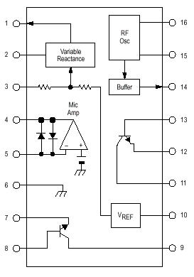
Encyclopedia of radio electronics and electrical engineering / Civil radio communications On the pages of amateur radio publications, there are often descriptions of various amateur radio and industrial CB radio stations. Everyone is already accustomed to the fact that a "typical" FM radio station with FM consists of a receiving path, necessarily built on microcircuits (mainly on K174XA26 and its analogues) and a transmitting path on transistors. Moreover, if microcircuits are allowed in the transmitting path, then no further than a microphone amplifier or modulator. All high-frequency components of the transmitter (master oscillator, power amplifier) are traditionally transistorized. However, MOTOROLA produces the MC2833 microcircuit, which is a complete path of a low-power FM MW transmitter. The microcircuit contains a microphone amplifier, a frequency modulator that sets a high-frequency oscillator (frequency stabilization by an external quartz resonator), and a single-stage power amplifier. To build a transmitter with a power of 20-30 mW, no additional transistor stages are required. The block diagram of the microcircuit is shown in Figure 1. The microcircuit is available in two package versions - MC2833D is a microcircuit in a miniature plastic package with plenary end leads for surface mounting, and MC2833R is a package similar to K561 with 16 pins. Both options have the same pinouts.
The microcircuit contains two high-frequency transistors of medium power, fully output (pins 11-12-13 and pins 7-8-9). On these transistors, power amplifier stages are built, on the first transistor (11-12-13) - a preliminary amplifier, and on the second (7-8-9) - a terminal one.
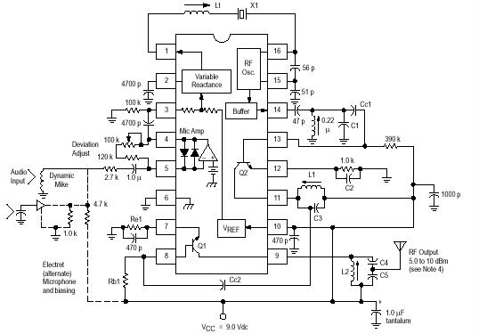
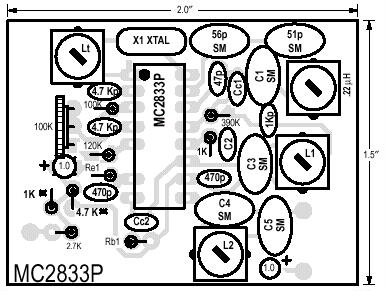
Figure 2 shows a real circuit of a low-power transmitter built on this chip. The frequency of the master oscillator is determined by the resonance frequency of the circuit, consisting of a quartz resonator Q1, an inductor L1 and a varicap, which is inside the A1 chip (it is output to pin 1 of A1). Coil 11, together with this varicap, forms a circuit that shifts the frequency Q1 from its nominal value. The degree of shift depends on the parameters of this chain. The modulating signal is taken from the M1 electret microphone and fed to the microphone amplifier-limiter, which is part of the microcircuit (to pin 5). From the output of the amplifier (pin 4), the signal goes to the modulator (pin 3), which is based on a varicap connected in series 11. Thus, frequency modulation is carried out. The master oscillator generates an RF voltage equal in frequency to the resonant frequency of the Q1-L1 varicap circuit of the microcircuit. The operating mode of the master oscillator for direct current can be set by selecting the value of the resistor R1. The RF voltage is removed from terminal 14 A1 and, through capacitor C5, is fed to the input of a preliminary power amplifier assembled on a transistor connected to terminals 11-12-13. Resistor R2 sets the bias voltage at the base of this transistor. Its emitter (pin 12) is connected to a common supply minus, and the L2-C6-C7 circuit is turned on in the collector circuit, tuned to the carrier frequency. The amplified signal is taken from this circuit through capacitances C6 and C7, which form a loop capacitance and an RF voltage divider by two. The output stage of the UMZCH is made on the second transistor (pins 7-8-9 of the microcircuit). The signal from the connection point C6 and C7 is fed to the base of this transistor along with a small bias voltage set by the resistive divider R6-R7. The choke DL1 is included in the collector circuit of this transistor. From the collector of the transistor (pin 9), the RF signal enters the antenna through the matching "P" circuit. For winding coils, frames with a diameter of 4 mm are used with trimming ferrite cores 100 VCh with a diameter of 2.6 mm. Coil L1 contains 16 turns, coil L2 - 6,5 turns, coil L3 - 8 turns. PETV-1 0,24 wire is used everywhere. Choke DL1 - factory DPM-01, 100 μH. The setting is traditional. Watch the signal from the output of the master oscillator at pin 15 A1, the signal entering the pre-amplification stage - at pin 14, the signal from the output of the preliminary PA - at pin 8. You can control the radiation of the antenna using a bulk coil connected at the input of the oscilloscope, or by field strength indicator, wave meter, etc. In the case of a matched load - on the equivalent of the antenna. Radioconstructor 8/2001, p.4-5. A typical circuit for switching on a microcircuit recommended by Motorola.
Table of element ratings for different frequencies:
Author: Konevich V.S.; Publication: N. Bolshakov, rf.atnn.ru
The world's tallest astronomical observatory opened
04.05.2024 Controlling objects using air currents
04.05.2024 Purebred dogs get sick no more often than purebred dogs
03.05.2024
▪ Rocstor Amphibious external drive protects data with encryption ▪ Hywind Tampen, world's largest floating wind farm, launched ▪ The reaction to a cigarette depends on the ideas about its composition.
▪ section of the site Grounding and grounding. Selection of articles ▪ article Milling glazing beads. Tips for the home master ▪ article What are lice? Detailed answer ▪ article Mirror for a telescope. Children's Science Lab ▪ article Fifteen matches are lifted one. Focus Secret
Home page | Library | Articles | Website map | Site Reviews
www.diagram.com.ua |


 Leave your comment on this article: