|
|
ENCYCLOPEDIA OF RADIO ELECTRONICS AND ELECTRICAL ENGINEERING Two-stage transmitter at 144 MHz. Encyclopedia of radio electronics and electrical engineering
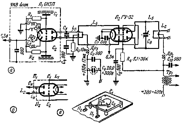
Encyclopedia of radio electronics and electrical engineering / Civil radio communications For long-distance communications in the range of 144-146 MHz, high frequency stability is required. This problem is solved most simply by using quartz stabilization, which is especially needed when establishing communications over a distance of 500-1000 km. However, short-range communications on this range are not uncommon and within 50-300 km. In this case, you can temporarily abandon the crystal stabilization and replace the quartz oscillator with a highly stable LC oscillator operating at a low frequency. So, for example, a Tesla circuit operating at a frequency of no higher than 7-8 MHz, subject to the necessary design conditions (quality of parts, electrical and thermal shielding, lamp type, etc.), provides stability only one order of magnitude lower than conventional quartz circuits. At the same time, the construction of the transmitter circuit remains the same as with quartz: a 7-8 MHz master oscillator, a number of multipliers, a pre-terminal amplifier and an output stage. Finally, there is another way to obtain sufficient stability in the range of 144-146 MHz - this is the use of enhanced parametric frequency stabilization directly at the operating frequency in two-stage circuits. To do this, it is necessary that the master oscillator work on high-quality circuits, have high mechanical strength, and not be overloaded by the subsequent cascade, in which all tendencies to self-excitation are eliminated. The fulfillment of these conditions is largely facilitated by push-pull circuits in the circuit of the master and output stages. According to this principle, a two-stage transmitter circuit was built and comprehensively tested using 6NZP and GU-32 lamps. The basis of the circuit is a VHF unit with an anode circuit from a quarter-wave two-wire line ("Radio" N 6, 1961), loaded with a grid circuit of the output stage on the GU-32 (see Fig. 1). The high power of the master oscillator, assembled on a 6N3P lamp, made it possible to do without tuning the GU-32 grid circuit, thereby increasing its frequency stability and reducing the tendency of the output stage to self-excitation. To eliminate asymmetry and the possibility of parasitic circuits and connections, the design of the transmitter is designed in the form of a ruler. The master oscillator on the 6N3P lamp operates at a fixed frequency in the range of 144-146 MHz, and only one output circuit is configured in the entire transmitter in the anode circuit of the GU-32 lamp. This not only simplifies the design, but also improves frequency stability by eliminating the mechanically unreliable tuning element at the fundamental frequency. Practice has shown that working in this range at a fixed frequency is beneficial, and sometimes decisive, as it allows you to wait and search for a correspondent only in a narrow section of the range, and also makes it possible to better recognize distant correspondents, etc.
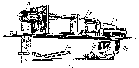
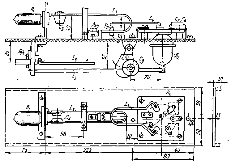
The design of high-frequency transmitter units Figure 2 shows a general view of the structure, and Figure 3 shows the general arrangement of all parts and components of the transmitter.
During construction, it should be borne in mind that the relative position of three nodes is essential: a master oscillator on a 6N3P lamp (its design and installation are fully consistent with the description in Radio No. 6 of 1961), the power amplifier input circuit (L4) and the anode circuit (L5C9L6) , in which both adjustment to the operating frequency and connection with the load are carried out. dimensions individual parts of the transmitter are shown in Fig.4. The ceramic panel of the GU-32 lamp is mounted on four racks, they can be made from any material. When powered by 6,3 V, the two extreme leads of the thread are connected together and grounded to the chassis with a wide copper strip. The GU-32 cathode is grounded with the same strip on the opposite side. This installation reduces the inductance in the cathode circuit and the tendency of the cascade to self-excite. The L4 connection loop in the GU-32 3 grid chain is made of 2 mm copper wire and is soldered directly to the grid petals on the lamp socket. The short-circuited end of the loop is attached to the R3C4 cell, which creates the necessary bias for the GU-32 lamp. Sufficient coupling with the master oscillator circuit L3C3 is obtained with a distance of the L4 coil from the chassis of the order of 32 mm. Above the socket, near the conclusions of the second grid and the filament outlet of the GU-32 lamp, there are capacitors C7, C8 (KCO-2), which are grounded to plate 2. The quenching resistance R4 ranges in value from 5,1 kΩ to 30 kΩ, depending on the source voltage nutrition. On the reverse side of the chassis is the anode circuit of the GU-32 lamp, which is mounted directly on the hard leads of the anodes of the GU-32 lamp, and on a bar made of any insulating material. Anode line 4 is made of 4 mm copper wire. At the open end, the wires are cut with a jigsaw, and a springy contact plate is soldered into the slot - clamp 5. At a distance of 65 mm from the end of the line, two washers with an M4 thread 6 are soldered to it, in which the movable stator plates 7 of the capacitor C9 are attached. Round stator plates (copper, brass) have an M3 thread in the center for the through screw 8 (M3). The rotor plate 9 is made of a strip of copper 0,5 mm and is mounted on a plate 10 of organic glass or other good insulator. The plate 10 is attached with two nuts to the axle 11 rotating in the column 12, which is attached to the base of the chassis under the line. This detail is similar in everything to the previously described tuning method for the VHF unit ("Radio" No. 6, 1961). The short-circuited end of the line is screwed with an M2 screw to plate 13 (hole). This plate is made of an insulating material and is attached to the chassis with an angle 14. A communication loop with the antenna and an anode choke (between points A and B) are attached to the same plate. The dimensions of the communication loop are selected depending on the quality and properties of the antenna used, approximately, its length is 100-120 mm. Setting and control of work During the tuning process, a fixed operating frequency is selected by changing the capacitance C3 (Fig. 1a) in the master oscillator. The normal distance between the C3 plates is about 1,2-1,1 mm and their slight change allows you to select any frequency in the range of 144-146 MHz. This setting is carried out using a graduated receiver or wavemeter with the GU-32 lamp turned on. To control the amount of excitation in the bias circuit of the grid of the GU-32 lamp, a milliammeter of 0-10 mA is included in the grid circuit and the connection of the L4 loop is selected so that the residual current is of the order of 3-4 ma. After that, when the anode and screen voltages are on, the resonance of the anode circuit is determined at the GU-32 by the decline in the anode current or the glow of the neon indicator when the capacitance C9 changes. If the resonance cannot be found, then the distance between the stator plates changes by rotating the screw 8 in the sleeve 6 (Fig. 4). The new position of the stator plates is fixed with a lock nut. Usually the distance between the plates is 3 mm. After these changes, by rotating the capacitor rotor, we again achieve resonance of the anode line, striving to ensure that the rotor plate is only half of its area covered by the stator. Such a "margin" of capacitance is necessary to adjust the circuit when the antenna is on. Having found the position of the resonance of the ps of the anode circuit, we turn off the anode and screen voltage and, by rebuilding the capacitor C9 near the resonance position, we observe the readings of the grid current of the GU-32 lamp. The arrow of the device should not fluctuate at the moment of passage through the resonance of the anode circuit. The fluctuations of the arrow indicate the existence of a parasitic connection between the grid and anode circuits, either due to their direct connection, or through the capacitance of the lamp. With such a connection and sufficient excitation, a neon lamp of the MN-3 type can light up on the anode circuit. Under such conditions, the output stage can be self-excited when the anode and screen voltages are connected, or when they change from modulation. The tendency of the output stage to self-excitation at the operating frequency can also be detected by the following features: 1) maximum return to the load (antenna, light bulb) but corresponds to the position of the lowest current and the anode circuit; 2) two settings appear in the receiver, close in frequency, one of which corresponds to the setting of the master oscillator, the second - to the output. The tendency to self-excitation due to coupling through the through capacitance can usually be eliminated by neutralizing the output stage. To do this, the grid and anode circuits are artificially connected in antiphase through additional capacitances Sn and Sn (Fig. 1), which are usually made of pieces of solid 1,5 mm wire rigidly attached to the grid leads on the GU-32 panel, which are then through the holes in chassis (Fig. 1, c) are brought to the anodes of the lamp outside the cylinder. By crossing the wires, the necessary anti-phase voltage is achieved, compensating for self-excitation. After the introduction of capacitances Cn, Cn, with the anode-screen voltage removed (but excitation supplied), the grid current of the GU-32 lamp is again checked when the anode circuit is tuned to resonance. If the grid current changes, then by changing the position of the wires relative to the mass of the lamp anodes or by shortening them, the readings of the grid device are completely independent of the setting of the anode circuit. A tendency to self-excitation or the occurrence of parasitic oscillations also appears in cases where the symmetry of push-pull circuits is violated. This must be taken into account when including a modulator or its individual components in the circuit, as well as introducing an antenna switch, measuring instruments, box walls, etc. The distances at which the named parts should be located should be two to three times the distance between the wires of the RF line , t.s. for GU-32 50-75 mm.
The table shows several operating modes of the RF unit. The master oscillator is powered by a stabilized 150 V source, its anode current ranges from 12 to 15,5 mA for the modes shown in the table. The values of the anode current Ia of the current of the screen grid Ic2 or the first grid Ic1 of the output lamp GU-32 are indicated as a fraction - the numerator corresponds to the value of currents without load; denominator - with the load on. An RF wattmeter, a tuned LC circuit with an incandescent bulb, was used as a load. The RF power data refer to the telegraph mode, the last two lines of Table 1 show data on typical operating modes of the GU-32 lamp. The most favorable mode when working with a telephone is obtained at Uc2=160-170 V; Ua-320-350B. It must be recalled that the initial experiments on establishing long-distance communications are best carried out in telegraph mode using a second local oscillator in the receiver or with tone modulation. The described circuit of a two-stage transmitter at 144 MHz has several advantages over conventional self-excited oscillators: 1) frequency stability increases so much that signals can be confidently received by receivers assembled according to a superheterodyne circuit; 2) efficiency increases significantly; 3) the design is easy to repeat, since, apart from 6N3P and GU-32 lamp panels, it does not contain purchased scarce parts. It seems to us that such schemes can be used to launch a broad attack on the two-meter range. Author: A. Kolesnikov (UI8ABD), Tashkent; Publication: N. Bolshakov, rf.atnn.ru
The world's tallest astronomical observatory opened
04.05.2024 Controlling objects using air currents
04.05.2024 Purebred dogs get sick no more often than purebred dogs
03.05.2024
▪ Universal power adapters 90 and 120 W for laptops
▪ section of the site Voltage stabilizers. Article selection ▪ article The great writer of the Russian land. Popular expression ▪ article How do objects move in space? Detailed answer ▪ article 144 MHz power amplifier. Encyclopedia of radio electronics and electrical engineering
Home page | Library | Articles | Website map | Site Reviews www.diagram.com.ua |


 Arabic
 Bengali
 Chinese
 English
 French
 German
 Hebrew
 Hindi
Hindi Italian
 Japanese
 Korean
 Malay
Malay Polish
 Portuguese
 Spanish
 Turkish
 Ukrainian
 Vietnamese


 Leave your comment on this article: