|
|
ENCYCLOPEDIA OF RADIO ELECTRONICS AND ELECTRICAL ENGINEERING A simple radio station in the range of 144 ... 146 MHz. Encyclopedia of radio electronics and electrical engineering
Encyclopedia of radio electronics and electrical engineering / Civil radio communications Technical data: Operating frequency range, MHz ...... 144-146
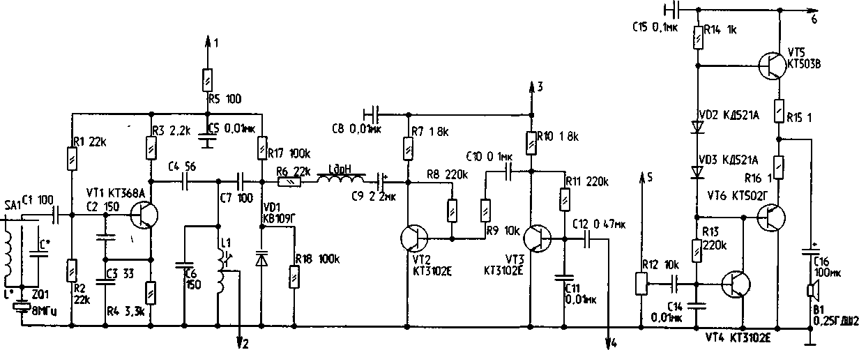
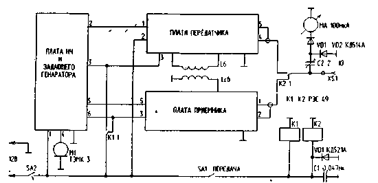
The radio station is designed to operate in the amateur frequency range 144 - 146 MHz with a shift between the transmit frequency and the receive frequency of 600 kHz. The main attention in the development of this radio station was given to the simplicity of design, the absence of a scarce element base, low labor intensity during tuning and good repeatability. The radio station operates on several fixed amateur band frequencies, depending on the quartz resonators available to the radio amateur. Schematic diagrams of the master oscillator and the low-frequency part of the radio station are shown in fig. one. The master oscillator is made according to the capacitive three-point circuit on a VT1 transistor of the KT368A type. Quartz resonator - at a frequency of 8 MHz is excited at the frequency of the main resonance. Inductance L* and capacitance C* are used to shift the frequency of the master oscillator in one direction or another to obtain several working channels. You can have up to seven of them in this scheme, if you set channels through 12,5 kHz in the range of 144 - 146 MHz, then the frequency shift of the master oscillator by one channel should be: 12,5 kHz: 18 = 0 kHz, because . the eighteenth harmonic at the operating frequency is highlighted. The master oscillator signal is allocated on the circuit L94, C1, tuned to a frequency of 6 MHz. Through pin 8 of the board, it enters the transmitter board for multiplication and amplification. Frequency modulation is carried out using a VD2 varicap of the KV1G type. The low-frequency signal is fed to the varicap through the chain R109, Ldr, C6 from the collector of the transistor VT9. The signal from the microphone, which is the TEMK-2 telephone capsule, is fed to output 3 of the board. A microphone amplifier is built on transistors VT4 and VT2 of the KT3E type. He has no special features. On transistors VT4 of the type KT3102V, VT5 - KT503V and VT6 - KT502G, an ULF receiver was built. Resistor R12 serves as a volume control. The low-frequency signal from the receiver board comes through pin 5 of the board. The ULF load is a dynamic head B1 of type 0.25GDSH2, you can use any other head with a winding resistance of 9 - 500m. On fig. 2 shows a diagram of the transmitter of the radio station. A resistive buffer amplifier is built on a VT1 transistor of the KT368A type. The cascade on the transistor VT2 type KT368A works as a frequency tripler. Its load is the circuits L2, C6 and L3, C8. They are tuned to 24 MHz. The cascade on the VT3 transistor of the KT368A type is also a frequency tripler. Its circuits L4, C12 and L5, C14 are tuned to a frequency of 72 MHz. The cascade on the VT4 transistor of the KT399A type is a frequency doubler. The circuit L6, C18 is tuned to a frequency of 144 MHz. Amplifiers are built on transistors VT5 of type KT399A and VT6 of type KT610A. They operate in mode C. Their circuits are also tuned to a frequency of 144 MHz. Through pin 4 of the board, the signal from the transmitter board goes to the switch relay. The receiving part of the radio station is shown in fig. 3. The receiver is built according to a superheterodyne circuit with a low intermediate frequency of 600 kHz. UHF is built on transistors VT1 and VT2 of the KP303E type. Coil L11 neutralizes the through capacitance of the amplifier. The circuits L12, C6 and L13, C9 are also tuned to a frequency of 144,6 MHz. A mixer is built on a VT3 transistor of the KT399A type. The local oscillator signal is fed to it through pin 4 of the board into the emitter circuit. In its collector circuit, an IF signal with a frequency of 600 kHz is allocated. The circuits L14, C10 and L15, C15 are tuned to this frequency. Through the L16 coupling coil, the IF signal is fed to the DA1 chip of the K174UR 1 type, which is multifunctional and performs the role of an amplifier, a frequency detector and a preliminary ULF. The reference circuit of the frequency detector L17, C20 is tuned to a frequency of 600 kHz. From pin 5 of the board, the low-frequency signal is fed to the volume control. The connection diagram of the radio station boards is shown in fig. four.
Switch SA1 is used to switch to transmission mode. In this case, the relays K1 and K2 are activated, switching the supply voltage and the antenna. The LCB coil is used to supply the local oscillator voltage to the receiver board. It is a straight insulated wire passing near the L6 coil of the transmitter board. The MA1 microammeter serves as an indicator of the output power of the transmitter. The radio station is made on three printed circuit boards of double-sided foil fiberglass with a thickness of 1,5 mm. Winding data of inductors are given in table. one.
The body of the radio station is best made of metal with good conductivity or soldered from fiberglass with a thickness of at least 3 mm. Boards in the case are placed in one row. The front panel of the radio has a volume control combined with a power supply switch, an antenna connector, a channel selector, a transmit-receive switch, a microphone jack, and an output power indicator. Radio station tuning should start with the master oscillator board. After applying voltage to the board, connect the RF voltmeter to point 2 of the board and adjust the circuit L1, C6 to the maximum output voltage. The number of inductances L* and capacitances C* is set according to the number of required channels. In this case, the frequency is controlled by pin 2 with a digital frequency meter. The radio station can also be made in a single-channel version. The microphone amplifier is tuned by selecting resistors R8 and R11 until an undistorted low-frequency signal is obtained at the VT2 collector. At the same time, a voltage of 4 mV and a frequency of 5 kHz is applied to output 1 of the board from the sound generator. In the ULF receiver, resistor R13 sets a voltage equal to half the voltage of the power source at the junction point of resistors R15 and R16. Then, by applying a voltage from the sound generator of 5 mV and a frequency of 50 kHz to pin 1 of the board, the output voltage at the dynamic head B1 is measured. It must be at least 1 V. This completes the board setup. Now proceed to configure the transmitter board. Before applying the supply voltage to the board, the equivalent of the antenna is soldered to pins 4 and 5 - a resistor with a resistance of 50 ohms and a power of 0,5 watts. From pin 2 of the master oscillator board, the RF voltage is applied to pin 1 of the transmitter board. An RF voltmeter and a frequency meter are connected to the VT3 base. The circuits L2, C6 and L3, C8 are tuned to a frequency of 24 MHz by rotating the cores, and the maximum output voltage is achieved. In the same way, the frequency tripler is tuned on the transistor VT3, only its circuits L4, C12 and L5, C14 are tuned to a frequency of 72 MHz, and the RF voltage is controlled on the basis of the transistor VT4. The frequency doubler circuit L6, C 18 is tuned to a frequency of 144 MHz. Then they proceed to setting up amplifiers on transistors VT5 and VT6. They are tuned by stretching and compressing the turns of the inductors L7, L8, L9, as well as by rotating the rotors of the trimmer capacitors C23, C26, C27, while trying to get the maximum output voltage on the antenna equivalent connected to terminals 4 and 5 of the board. Then proceed to setting up the receiver board. Before applying voltage from the power source to the board, the local oscillator voltage is applied to pin 4 of the board using a communication loop. A voltage with a frequency of 1 MHz from a VHF generator is applied to pin 144,6 of the board (its amplitude should be about 50 mV and the deviation should be 5 kHz), modulated by a tone of 1 kHz. An oscilloscope is connected to pin 5 of the board. Having soldered the capacitor C9, an RF voltage with a frequency of 3 kHz, an amplitude of 600 mV and a deviation of 150 kHz is applied to the base of the transistor VT5. Adjust the circuits L14, C10, L15, C15 and L17, C20 to the maximum output voltage, while gradually reducing the input voltage. Then, having restored the connection of the capacitor C9, the UHF circuits L10, C2, L12, C6 and L13, C9 are tuned to a frequency of 144,6 MHz by rotating the rotors of the corresponding capacitors. Coil L11 achieves the absence of excitation of the UHF cascade. The sensitivity of the receiver from input 1 of the board must be at least 0,3 μV, while at output 5 of the board there must be a low-frequency voltage with a frequency of 1 kHz and an amplitude of at least 100 mV. This completes the setup of the receiver board. Since the radio station operates with a shift between the transmit frequency and the receive frequency of 600 kHz, the frequency of the quartz resonator of the second radio station, which will be paired with the first, needs to be slightly shifted up in any way known to the radio amateur. Let's calculate this frequency. Since the radio station uses the 18th harmonic of a quartz resonator with a frequency of 8 MHz, then: 144,6 MHz: 18-9,0333 MHz, therefore, the frequency of the quartz resonator should be shifted by 33,3 kHz or find a quartz resonator to this frequency. During the tests, the radio showed very good results. When working with the same type of radio station and using outdoor antennas of the "quarter-wave pin" type, installed at a low altitude, the connection was stable at a distance of up to 50 km. When installing radio stations on cars, communication was at a distance of up to 15 km. This radio can also be used to work through repeaters. For purchase of printed circuit board drawings, please contact the author. Author: V. Stasenko (RA3QEJ), Voronezh region, Rossosh; Publication: N. Bolshakov, rf.atnn.ru
Machine for thinning flowers in gardens
02.05.2024 Advanced Infrared Microscope
02.05.2024 Air trap for insects
01.05.2024
▪ Anti-radiation suit for the NASA lunar mission ▪ Data transmission through black holes ▪ Assessment of emotional stress in the cinema ▪ Greenhouse in which it is cool
▪ section of the site Palindromes. Article selection ▪ Visakhadatta article. Famous aphorisms ▪ article Where do panama hats come from? Detailed answer ▪ article Crossing ford. Travel Tips ▪ GP article for 80 meters. Encyclopedia of radio electronics and electrical engineering ▪ article Bridge transistor rectifier. Encyclopedia of radio electronics and electrical engineering
Home page | Library | Articles | Website map | Site Reviews www.diagram.com.ua | |||||||||||||||||||||||||||||||||||||||||||||||||||||||||||||||||||||||||||||||||


 Arabic
 Bengali
 Chinese
 English
 French
 German
 Hebrew
 Hindi
Hindi Italian
 Japanese
 Korean
 Malay
Malay Polish
 Portuguese
 Spanish
 Turkish
 Ukrainian
 Vietnamese


 Leave your comment on this article: