|
|
ENCYCLOPEDIA OF RADIO ELECTRONICS AND ELECTRICAL ENGINEERING Radio station Astra-1-FM-CB. Encyclopedia of radio electronics and electrical engineering
Encyclopedia of radio electronics and electrical engineering / Civil radio communications The radio station operates on one fixed frequency in the 27 MHz band (in this case 27,12 MHz), with frequency modulation. It has quartz frequency stabilization of both the receiver and the transmitter. With the same type of radio station, it provides communication in open areas within a radius of up to 3 km, in urban areas up to 1 km, depending on specific circumstances.
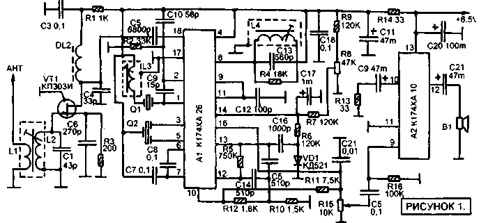
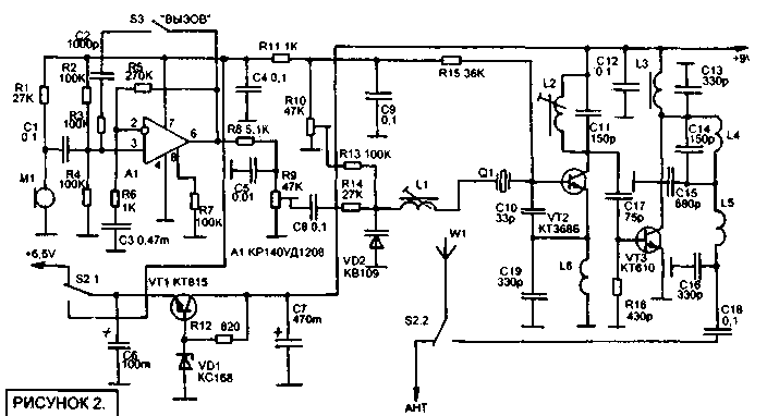
A schematic diagram of the receiving path is shown in Figure 1. It is assembled on the basis of a specialized K174XA26 microcircuit, designed to work in the IF paths of radiotelephones. The microcircuit contains a local oscillator, a frequency converter, an IF path, a frequency detector, and a noise reduction system that blocks the low-frequency output of the microcircuit in the absence of a useful input signal. The input signal from the antenna through the switch S2.2 (Figure 2) is fed to the input circuit L2C1 (Figure 1) through the coupling coil L1. Next, the signal is fed to the input of the URC, made on a field-effect transistor VT1. The purpose of this stage is to match the high output impedance of this circuit with the relatively low-resistance input of the A1 microcircuit. The local oscillator frequency of the A1 microcircuit is determined by the resonance frequency of the quartz resonator Q1, the frequency of which should differ by 465 kHz from the channel frequency (in this case, Q1 by 27,575 MHz). The L3 coil serves to facilitate the launch of the local oscillator, and with a good resonator and microcircuit, it may not be required at all, but as practice shows, some instances of resonators and microcircuits require this coil. The intermediate frequency signal, as well as a complex of side frequencies - conversion products, is selected at pin 3 A1. Then the piezoceramic filter Q2 extracts a signal with a frequency of 465 kHz from this complex and it enters the input of the IF path through pin 5. The L4C13 circuit is set to IF, it works in the phase-shifting circuit of the frequency detector. Resistor R4 lowers the quality factor of the circuit and thus serves to reduce distortion during detection. From the output of the detector, the low-frequency signal is fed to the detector of the noise reduction system on the diode VD1. In the absence of an input signal, the level of high-frequency noise increases, as a result of which the internal trigger of the microcircuit is activated and shunts the volume control R16 through pin 15, lowering the AF voltage on it to zero. The threshold for the noise reduction system can be set using resistor R8. The low-frequency amplifier is made on the A2-K174XA10 chip. This microcircuit has the full path of a pocket AM broadcasting receiver, but due to the high quality of the UZCH included in it and the relatively low cost of the microcircuit, it has become widespread in amateur radio technology as an UZCH. At the same time, the remaining stages of the microcircuit are not used in any way. The schematic diagram of the transmitter is shown in Figure 2. It is based on the transmitter of the ASTRA-4SV radio station (j. Radio constructor 07-1999, p. 8-12). The transmitter is simplified in the sense that the channel switch is eliminated and only one quartz resonator is used. Coils of the receiving path L1-L3 are wound on frames with a diameter of 5 mm with tuning cores with a diameter of 2,5-2,8 mm and a length of 12 mm from 100-NN ferrite. Ready-made frames are used from the contours of the HF bands of portable broadcasting receivers, but more accessible frames can also be used - from the circuits of the SMRK of USST TVs, but in this case it will be necessary to slightly modify the layout of the printed circuit boards. Coil L2 contains 10 turns, L1 is wound on the surface of L2 and contains 3 turns L3 contains 16 turns. Wire type PEV 0,2-0,3. Coil L4 together with capacitor C 13 is a ready-made IF circuit from a broadcasting portable receiver with an IF equal to 465 kHz. It is clear that the capacitance C13 may be different, but it must be exactly the same as in the receiver circuit from which the coil is used. Choke DL2 - ready-made factory DPM-01 for 100 μH. The transmitter coils L1 and L2 have the same frames as the high-frequency coils of the receiving path. L1 contains 18 turns, L2 - 5 turns, PEV wire 0,2-0,3. Coils L4-L6 are frameless, they have an inner diameter of 3 mm. L4 - 7 turns, L5 - 9 turns, L6 also 9 turns. Wire PEV 0,3-0,4. Coil L3 is a choke, it is wound on a K7X4X2 ferrite ring made of 50 VCh ferrite, contains 15 turns of PEV 0,2-0,3. The antenna is spiral, wound on a piece of internal insulation of a coaxial cable with a diameter of 9 mm and a length of 250 mm. It contains, starting from the connector, 80 turns of wire PEV 0,3-0,4, tightly, and then evenly along the remaining length of another 30 turns of this wire. Polyvinyl chloride cambric is tightly stretched onto the finished antenna. The receiver's piezoceramic filter is small-sized from a domestic radio receiver with an IF frequency of 465 kHz. You cannot use an imported one, since it will be at a frequency of 455 kHz. Speaker - any small-sized, for example, from the same radio receiver, a microphone - an electret microphone with a built-in amplifier from an imported handset. Installation is carried out on two printed circuit boards, one for the receiving path, the other for the transmitter. For the receiving path, a board with one-sided foil is used. For the transmitter - two-sided, on it the foil from the side of the parts is used as a common minus power bus. On the circuit board, crosses mark the places where soldering goes to the foil from the side of the parts. Receiver circuit board (parts side view) Receiver circuit board (wire side view) Author: Andreev S.; Publication: N. Bolshakov, rf.atnn.ru
A New Way to Control and Manipulate Optical Signals
05.05.2024 Primium Seneca keyboard
05.05.2024 The world's tallest astronomical observatory opened
04.05.2024
▪ LTC5508 Subminiature Broadband Power Detector ▪ DNA-Based Programmable Computing Device
▪ site section Acoustic systems. Article selection ▪ article The moor has done his job, the moor can go. Popular expression ▪ article Why do we stop growing? Detailed answer ▪ article Common colza. Legends, cultivation, methods of application
Home page | Library | Articles | Website map | Site Reviews www.diagram.com.ua |


 Arabic
 Bengali
 Chinese
 English
 French
 German
 Hebrew
 Hindi
Hindi Italian
 Japanese
 Korean
 Malay
Malay Polish
 Portuguese
 Spanish
 Turkish
 Ukrainian
 Vietnamese


 Leave your comment on this article: