|
|


 Arabic
 Bengali
 Chinese
 English
 French
 German
 Hebrew
 Hindi
Hindi Italian
 Japanese
 Korean
 Malay
Malay Polish
 Portuguese
 Spanish
 Turkish
 Ukrainian
 Vietnamese
|
ENCYCLOPEDIA OF RADIO ELECTRONICS AND ELECTRICAL ENGINEERING Spatial selection of signals. Encyclopedia of radio electronics and electrical engineering
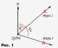
Encyclopedia of radio electronics and electrical engineering / Civil radio communications Using antennas with a noticeably non-circular radiation pattern will reduce interference from transmitters using the same frequency as the radio you want to use. The same antennas make it possible to determine the direction to the radio station - to find it, which is necessary to determine either your location or the location of the radio station. This article talks about how this can be done with a loop antenna. You can determine the direction of arrival of radio waves using a direction finder - a radio receiver that is equipped with a directional antenna. Radio direction finding makes it possible to solve a number of important practical problems, mainly of a navigational nature. For example, if you install a direction finder receiver on some moving object (airplane, ship, etc.), whose location is unknown, then, having determined with its help the direction of arrival of radio waves from two or three known radio transmitters, you can also find out the place in which the object of interest is currently located. How this is done is illustrated in Fig. 1.
First determine the angle f1 between the direction of the meridian N and the direction of arrival of the radio signal from the first transmitter ("Mayak 1"). Then on the navigation map through the point where this transmitter is located, a line (bearing) is drawn at an angle f1 to the meridian. The same constructions are carried out for the second transmitter ("Mayak 2"). The point of intersection of the bearings will correspond to the location of the moving object. Often radio direction finding solves other problems. With the help of direction finders located in different places, the direction of arrival of a radio signal from the same transmitter is determined and, having plotted the bearings obtained in this way on the map, the location of the transmitter itself is found at the point of their intersection (Fig. 2).
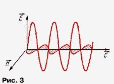
To determine the direction of arrival of the radio signal, it was proposed earlier than others to use a loop antenna. To understand its directional properties, let us recall the structure of an electromagnetic wave, which is illustrated in Fig. 3. This figure can be found in any textbook on radio engineering.
An electromagnetic wave consists of electric E and magnetic H fields oscillating with the frequency of the transmitter. These fields are perpendicular to each other, and since the wave itself is transverse, they are also perpendicular to the direction of its propagation C. The direction of the electric field vector E determines the polarization of the wave, which can be horizontal, vertical and arbitrary. At long and medium wavelengths, the earth and especially the sea have good electrical conductivity, so waves with horizontal polarization near their surface (and this is where the receiver is usually located) are greatly attenuated. For this reason, all transmitters operating in the long-wave and medium-wave ranges emit vertically polarized waves, the electric field of which at the conducting surface is always perpendicular to it. The loop antenna is a flat coil, the number of turns of which depends on the range in which the antenna operates. At shorter wavelengths, it may contain one or more turns, and at longer wavelengths it is much larger. According to the law of electromagnetic induction, a radio wave arriving at the frame induces an EMF in it, but for this to happen, the magnetic field must penetrate the coils of the frame. Let's turn to Fig. 4, which shows a top view of a vertical loop antenna. If the radio wave passes along the axis of the frame (f=0° or 180°), then its magnetic field does not penetrate the turns of the frame and there is no reception. If the wave is perpendicular to the axis of the frame (f=90° or 270°), then the signal induced in its turns is maximum. The EMF induced in the frame by radio waves arriving at other angles f to its axis is proportional to the sine of these angles. The graph of the dependence of the EMF induced in the frame on the angle of arrival of the wave is called the radiation pattern. In polar coordinates, it has the form of two circles touching each other at the location of the frame (Fig. 4).
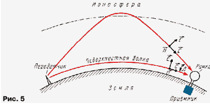
Direction finding using a loop antenna is best done not at the maximum, but at the minimum reception, since the latter is much more pronounced and the direction finding is more accurate. The radiation pattern has two minima, so the bearing is determined ambiguously. Most often, it is known which side the transmitter is located on, and if this information is not available, then you can use one of the methods to obtain a unidirectional radiation pattern. For example, use a frame and an omnidirectional whip antenna for reception and, by adding signals from two antennas with certain amplitudes and phases (the amplitudes must be equal, and the phases are shifted by 90 °), compensate for one of the maxima of the frame radiation pattern, increasing the other accordingly. In this case, the so-called cardioid radiation pattern will be obtained, which has one "blurred" maximum and one sharp minimum. Everything would be fine if the radio waves came to the receiver, propagating along the surface of the Earth. But this way comes the surface wave, enveloping the Earth due to diffraction. The range of its propagation, as a rule, is several hundred kilometers. But at night, at medium and long waves, another spatial wave appears, due to reflection from the ionosphere and propagating over thousands of kilometers. This happens because the upper layers of the atmosphere (ionosphere) are strongly ionized by solar and cosmic radiation and, as a result, they conduct electric current and reflect radio waves. In the daytime, in the long-wave and medium-wave ranges, ionospheric waves are strongly absorbed. At short wavelengths, absorption is less, and ionospheric, sky waves arrive at any time of the day. The ionospheric wave arrives at the frame somewhat from above, at an angle b to the horizon (Fig. 5).
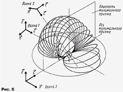
The polarization of a sky wave is unpredictable due to the rotation of the polarization plane in the ionospheric plasma magnetized by the Earth's magnetic field. The presence of sky waves at the receiving point leads to an error in direction finding, which has received the special name of "night" error. To understand how it arises, let's try with the help of Fig. 6 build a volumetric radiation pattern of the loop antenna. If a vertically polarized wave 1 comes from a horizontal direction at an angle of f=90° and b=0°, then the reception is maximum. If you increase the angle b (wave 2 in Fig. 7), the signal strength will not change, since the magnetic field vector of the wave H will still remain parallel to the axis of the frame, and the magnetic field itself will penetrate its coils. Reception will be maximum even when the wave falls vertically downwards, provided that the vector H is parallel to the axis of the frame. These considerations make it possible to draw a three-dimensional radiation pattern of the frame in the form of a toroid ("donut"), put on the axis of the frame. Naturally, only half of this toroid will rise above the Earth's surface, as shown in Fig. 6. Such a diagram is given in many textbooks on antennas. The diagram has a horizontal axis of minimum reception, coinciding with the axis of the box.
The picture changes for wave 3, the direction of arrival of which coincides with the axis of the frame. Such a wave will not induce an EMF in it, since the vector H is perpendicular to the axis of the frame and the magnetic field does not penetrate its coils. With an increase in the angle b, i.e., the angle of arrival of the wave, the vector H will remain in the plane of the frame and will be perpendicular to its axis. Reception in this case will still be absent! Now it turns out not an axis, but a vertical plane of minimum reception, and the axis of the frame lies in this plane. The volumetric radiation pattern takes the form of two hemispheres lying on both sides of the frame. But what about a sheerly falling wave - after all, in the previous example it was accepted, but now it is not? the reader will ask. That's right, a sheer incident wave is accepted if its vector H is parallel to the axis of the frame, and not accepted if it is perpendicular to it. Thus, the frame is sensitive to the polarization of incoming spatial waves. Their unpredictable polarization leads to "smearing" of the minima of the directivity pattern and to rather significant bearing errors. Loop antennas are small, simple in design and have a number of other advantages. Because the loop coil's impedance is inductive, it can be tuned to resonate with the fluctuations in the received signal by simply adding a variable capacitor. The resulting oscillatory circuit, firstly, increases the amplitude of the received signal and, secondly, suppresses the signals of unnecessary stations operating at other frequencies, i.e., increases the selectivity of the receiver. Another advantage of the frame is that it responds to the magnetic field component, while the near field of interference from power frequency networks contains most often the predominant electrical component. Thus, reception on a magnetic loop antenna in urban conditions is usually more noise-resistant than on electric, dipole and wire antennas. There is no such difference in rural areas. And one more thing: the magnetic component of the radio wave penetrates inside buildings at least a little, by fractions of a wavelength, but still deeper than the electric one. Therefore, it is better to make indoor antennas magnetic. The directional properties of the frame make it possible in many cases to eliminate or reduce interference if the source of interference is localized and the interference radio waves come from one specific direction. The axis of minimum reception of the frame in this case must be directed to the source of interference. In this case, the useful signal may also be attenuated, since the direction of its arrival will no longer correspond to the maximum of the radiation pattern, however, the signal-to-noise ratio may improve significantly. To verify this in practice, turn on a portable receiver with a ferrite magnetic antenna (its properties are similar to those of a frame). Then place the receiver near a working TV or computer (sources of significant interference) and try turning the receiver in your hands to change the orientation of the magnetic antenna. In some of its positions, interference will be significantly weakened. Author: V.Polyakov, Moscow
Machine for thinning flowers in gardens
02.05.2024 Advanced Infrared Microscope
02.05.2024 Air trap for insects
01.05.2024
▪ Compact camera Olympus Stylus SH-1 ▪ Film and the composition of the air of the auditorium ▪ Television and school grades
▪ section of the Antenna website. Article selection ▪ article by Charles Lam. Famous aphorisms ▪ Asafoetida article. Legends, cultivation, methods of application ▪ article Multiband vertical antenna. Encyclopedia of radio electronics and electrical engineering
Home page | Library | Articles | Website map | Site Reviews
www.diagram.com.ua |


 Leave your comment on this article: