|
|


 Arabic
 Bengali
 Chinese
 English
 French
 German
 Hebrew
 Hindi
Hindi Italian
 Japanese
 Korean
 Malay
Malay Polish
 Portuguese
 Spanish
 Turkish
 Ukrainian
 Vietnamese
|
ENCYCLOPEDIA OF RADIO ELECTRONICS AND ELECTRICAL ENGINEERING Quasi-touch power switches. Encyclopedia of radio electronics and electrical engineering
Encyclopedia of radio electronics and electrical engineering / Civil radio communications Ease of use of radio equipment is one of its indispensable quality indicators. This article describes a simple improvement that will allow you to more rationally use the capabilities of the radio. Most small-sized radios have power switches combined with a volume control. This solution simplifies the design, but is inconvenient in practice. In order to turn off the receiver, you have to turn the volume control knob, violating the previously set volume level control and spend some time to set the same level when turned on. It should be noted that a few decades ago, a similar switch, combined with one of the adjustments, was widely used in household radio equipment, but today it is clearly outdated. Modern equipment is controlled differently - by convenient quasi-touch switches, when the impulse from the short-stroke button is processed by the microprocessor. Of course, in simple receivers there is no microprocessor control, nevertheless, a power switch controlled by a slight push of a button can be built into it by assembling a simple device according to one of the options below. Pocket-type radios are powered primarily by two limited-capacity AA-type AA cells. This imposes rather stringent requirements on the device being developed in terms of efficiency, the absence of voltage losses in the switching circuit. In addition, the dimensions of the switch block must be minimal in order to be able to embed it in the body of a miniature receiver. A possible circuit of a quasi-sensor switch that satisfies such requirements is shown in fig. 1. It is based on a counting trigger, made on one of the two D-flip-flops of the K564TM2 chip. The trigger is obtained by connecting the inverted output to the information input D, which turns the clock input C into a counting one. The trigger output signal is applied to the base of the transistor switch VT1 through the HL1 LED, which acts as a power indicator. Switch SA1 - the mentioned standard switch of the radio receiver, combined with the volume control (not shown in the diagram). The SB1 button controls the quasi-sensor switch - its closing contact connects the "plus" of the power supply to the input C of the DD1 trigger, forming a counting pulse. The initial zero potential at this input determines the R1C1 circuit, which, in addition, prevents possible interference and contact bounce.
The operation of the device is based on the logic of the trigger - its output state will be changed each time to the opposite when a positive voltage drop of the pulse arrives at input C. Suppose that the initial state of the trigger is such that its direct output is log. 1. Then the base-emitter voltage of the transistor VT1 is zero, the transistor is closed, the radio is turned off. When you press the SB1 button, the front of the pulse at the input C switches the trigger to the log 0 state. At the same time, the output. 1 chip voltage is close to the supply voltage. The HL1 LED circuit - the B-E junction of the transistor begins to flow a current sufficient to ignite the LED and open the VT1 transistor - the load (receiver) through the low resistance of the E-K will be connected to the power source. At the same time, the HL1 LED indicates the inclusion of the radio. The next press of the SB 1 button returns the trigger to its original state, the transistor VT1 closes, the HL1 LED goes out - the receiver is turned off. In this state, it can be indefinitely, until the next press of the SB1 button. The power consumed by the DD1 chip (CMOS structure) in static mode is negligible. As a result, in the "off" state, the device practically does not consume current. In the "on" state with the open transistor VT1, the total current consumption increases by no more than 1 mA, but the power indicator LED also works - a feature that deserves attention. Low costs, and therefore high efficiency, are obtained through the use of the KT208V transistor, which has a low saturation voltage - the normalized value at a current of 300 mA is 0,3 V, and the measured value at a current of 25 mA did not exceed 0,05 V. Even higher efficiency has a switch, the diagram of which is shown in Fig. 2. Here, a special field-effect transistor KP505A with a low threshold voltage and an open channel resistance of the order of tenths of an ohm is used as a switching element. Its insulated gate control circuit has an infinitely large input impedance and therefore draws no current. Due to this, as well as the characteristics of the microcircuit, properties are provided that are close to those of a mechanical switch - "zero" power consumption in both modes, no losses in the closed state of the "contact".
In accordance with its structure, the field-effect transistor VT1 is included in the break of the "negative" power wire. It is open when on the pin. 1 chip high level, and closed - in the opposite state. Otherwise, the operation of the device does not differ from the operation of the previous one. Although the normalized lower voltage limit for CMOS logic chips is 3 V, the trigger works stably when the supply voltage drops to 1,5 V, and some deterioration in performance (speed and others) does not matter in this case. If you select a transistor VT1 for the device according to the circuit in Fig. 1 with the parameter h21e>200, and for the device according to fig. 2 - with a minimum threshold voltage (-1,6 V), then the switch according to the circuit in fig. 1 is operational when the supply voltage drops to 1,8 V, and according to fig. 2 - up to 1,6 V. Without the selection of transistors, both devices work well in the range of 2 ... 3 V. A slightly higher allowable voltage in the switch according to the circuit in fig. 1 can be explained by the presence of the HL1 LED, but there is also an advantage - the LED acts as an indicator for turning on the receiver and discharging the battery: the batteries should be changed when it goes out.
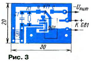
The microcircuit can be replaced with a similar one from the 561 series, however, this will increase the dimensions and require reworking the printed circuit board. The KT208 transistor is applicable with the letter index E. The best replacement for it is KT529A. Button SB1 - short-stroke non-fixed, from imported radio equipment, dimensions 6x6x3 mm with a stem with a diameter of 3 mm. It is convenient in that it can have a stem of different lengths. Of course, you can use other buttons, including those of domestic production (for example, the MP7 microswitch). LED HL1 should have a maximum brightness at a current of 1 mA. Good results here are given by imported red LEDs. It is undesirable to use emitters of a different color, since they have a larger forward voltage drop and lower brightness. Resistor - MLT-0,125, capacitor - any miniature ceramic. The device according to fig. 2 is assembled on a single-sided printed circuit board by surface mounting (Fig. 3). The printed circuit board is connected by flexible wires to the battery and the plus and minus terminals to the receiver board. The regular power switch SA1 is left in the circuit (it is permanently closed), it does not interfere with the operation of the quasi-sensor, and sometimes it can be useful, for example, during long-term storage of the receiver, transportation, etc. A prerequisite for connecting the device is to disconnect one of the receiver's power buses directly at the battery compartment: positive - for the device according to the scheme of fig. 1 and negative - for the device according to the scheme of fig. 2. Switches do not require settings. Embedding in a radio receiver consists in installing a finished board (for example, on brackets) in any free place so that the rod protrudes 1,5 ... 2 mm above the surface of the housing, in which a hole with a diameter of 3,5 mm should be pre-drilled. The said button does not require any special pushers, although, if desired, they can, of course, be made for decorative purposes. The reliability of the developed devices is very high: for the entire period of operation, there were no false positives and other failures in the transistor radio. The scope of use of devices is much wider than small-sized receivers. They can also work normally with a supply voltage of 9 ... 12 V, for this it is enough only in the circuit according to fig. 1 connect a limiting resistor between the cathode of the HL1 LED and the base of the transistor VT1 until the current in this circuit is 1 mA. With a supply voltage of 9 V, it may be necessary to select the capacitor C1 for a clear operation. The power of the switched equipment depends on the allowable current through the VT1 transistor, which is 150 mA or 1 A with the KT529A transistor (see Fig. 1) and 1,4 A (see Fig. 2), respectively. Author: A.Pakhomov, Zernograd, Rostov region
The world's tallest astronomical observatory opened
04.05.2024 Controlling objects using air currents
04.05.2024 Purebred dogs get sick no more often than purebred dogs
03.05.2024
▪ The moon may have been responsible for the sinking of the Titanic ▪ Chip TDA15600 to control the LCD TV screen
▪ site section Voltage converters, rectifiers, inverters. Article selection ▪ article Soul high impulses. Popular expression ▪ article What is the difference between timpani and drum? Detailed answer ▪ article Machinist of dust pumps. Standard instruction on labor protection
Home page | Library | Articles | Website map | Site Reviews
www.diagram.com.ua |

 Leave your comment on this article: