|
|


 Arabic
 Bengali
 Chinese
 English
 French
 German
 Hebrew
 Hindi
Hindi Italian
 Japanese
 Korean
 Malay
Malay Polish
 Portuguese
 Spanish
 Turkish
 Ukrainian
 Vietnamese
|
ENCYCLOPEDIA OF RADIO ELECTRONICS AND ELECTRICAL ENGINEERING Radio station TAIS-RM41. Encyclopedia of radio electronics and electrical engineering
Encyclopedia of radio electronics and electrical engineering / Civil radio communications We are already accustomed to the fact that almost all modern radio-electronic equipment is produced, as a rule, by foreign companies. In particular, the CB communication equipment available for sale in our market is represented by such brands as Alan, Dragon, Yosan, etc. But recently, domestic manufacturers are also trying to compete with foreign ones. Today we will talk about a car radio station manufactured by the Tais company, which, in terms of its characteristics, is close to foreign analogues, and its price is somewhat lower. The RM41 radio station is designed for searchless, tuningless radio communication in simplex mode in the 27 MHz band (grids C and D) with frequency modulation. It has certificate No. OS/1-RS-836. The appearance of the radio station is shown in fig. 1, and the view with the cover removed is shown in Fig. 2.
Like most modern radio stations, Tais-RM41 "can operate in the European and Russian frequency grids. It is possible to scan over the range with a stop on a busy channel. There is a memory for three user-programmed channels, scanning through memory channels, remembering the last working channel. In the "Monitor" mode, the squelch is forced to turn off to control weak signals.There is a tone call in the transmission mode, as well as a megaphone mode. It is possible to install a CTCSS module with 16 tone options. Its use will allow to implement a selective call. The squelch will only respond to CTCSS equipped radios with the same tone used on the receiving side. Instead of the CTCSS module, an address call board using DTMF signals can be installed. Microprocessor control provides the ability to reprogram operating frequencies, change the operation algorithm, control the station from external devices through the built-in interface connector. The factory circuit diagram of the radio station is shown in fig. 3. A frequency synthesizer is assembled on the DD1 chip, which generates signals for the transmitter master oscillator and receiver local oscillator in accordance with the selected channel. The synthesizer is controlled by the DD2 microprocessor controller (PIC controller PIC16C64). Its clock frequency is set by a BQ3 quartz resonator at 32 Hz. Such a low frequency was chosen in order to reduce interference to the radio receiver. The signals from the buttons on the front panel and from the transmit and dial tone buttons on the PTT go to the controller. It also transmits control codes to the synthesizer (in the receive and transmit modes), turns on the power of the receiving path, and sends a control signal to the master oscillator to turn on the transmitter.
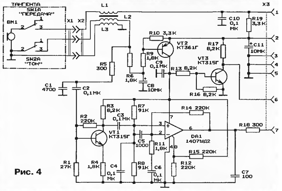
Through the parallel port DD3, the signals from the controller are sent to the LED indicator HG1. The current settings (the last working channel, etc.) are recorded in the non-volatile memory DD4. The radio station receiver is made according to a superheterodyne scheme with double frequency conversion. The input signal from the antenna is fed to the URF (transistor VT1). Diodes VD1, VD2 protect the input stage of the receiver in transmission mode. The first mixer is made on a DA1 chip, and the local oscillator is made on a VT4 transistor. The local oscillator controls the signal from the DDL frequency synthesizer. At the output of the mixer, the L4C10C11 circuit is turned on, which selects the first IF signal (10,7 MHz). This signal is fed to the BF1 piezoceramic filter with a bandwidth of 150 kHz, and then to the second mixer (IC DA2). A quartz local oscillator with a frequency of 10 kHz is built on the same microcircuit. From the output of the mixer DA2, the signal of the second intermediate frequency (455 kHz) is fed to the piezoceramic filters of the main selection BF2 and BF3 with a bandwidth of 7...10 kHz. Between them is an intermediate frequency amplifier (IF) on a transistor VT2. The DA3 chip performs the functions of a limiting amplifier, a frequency detector and a preliminary ULF. The audio frequency amplifier is assembled on a DA6 chip. The diagram of the microphone board is shown in fig. 4. The speech signal from the BM1 microphone is fed to the microphone amplifier (DA1). The generated signal is fed through a low-pass filter (R49, C43 according to the diagram in Fig. 3) and a diode limiter VD10VD11 to a smooth range generator (transistors VT6, VT7) for frequency modulation. You can adjust the frequency deviation with a resistor RV1. The GPA is turned on by applying a positive bias to the base of the VT6 transistor through the R38C58 smoothing filter, which eliminates impulse noise.
This generator generates a signal with a frequency F GPD equal to half the operating frequency. Through the capacitor C53, it enters the VCO input of the frequency synthesizer DD1, where it is compared with a given frequency. If the frequencies do not match, the voltage at the output PDOUT (pin 13 DD1) changes in the direction of decreasing or increasing, depending on which frequency is higher. This voltage is supplied to the VD5, VD6 varicaps included in the GPA circuit. A change in the capacitance of the varicaps leads to a change in the frequency F. The L9C56C57 circuit highlights the signal of the second harmonic of the GPA frequency. This signal is amplified by a three-stage amplifier (transistors VT7-VT9) and fed through the output filter L12-L14, C68-C73 to the antenna socket X1. Author: S. Vakhrushev, Moscow
Machine for thinning flowers in gardens
02.05.2024 Advanced Infrared Microscope
02.05.2024 Air trap for insects
01.05.2024
▪ Which language is the easiest ▪ Washer-dryer TCL Twin Cabin Q10
▪ section of the site Amateur Radio Technologies. Selection of articles ▪ article by Samuel Taylor Coleridge. Famous aphorisms ▪ article Where and when did cricket and baseball appear? Detailed answer ▪ article Head of the Cabinet of Medical Statistics. Job description ▪ article Ultra-low voltage LED emitters. Encyclopedia of radio electronics and electrical engineering ▪ article Simple FM receiver. Encyclopedia of radio electronics and electrical engineering
Home page | Library | Articles | Website map | Site Reviews
www.diagram.com.ua |


 Leave your comment on this article: