|
|


 Arabic
 Bengali
 Chinese
 English
 French
 German
 Hebrew
 Hindi
Hindi Italian
 Japanese
 Korean
 Malay
Malay Polish
 Portuguese
 Spanish
 Turkish
 Ukrainian
 Vietnamese
|
ENCYCLOPEDIA OF RADIO ELECTRONICS AND ELECTRICAL ENGINEERING Amateur radio receiver for 160 meters. Encyclopedia of radio electronics and electrical engineering
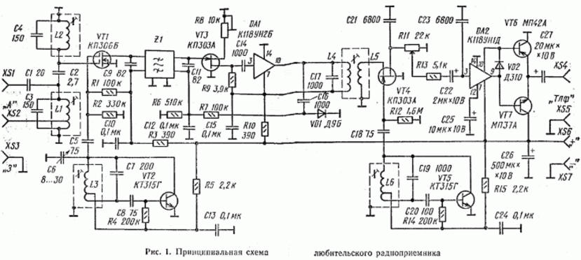
Encyclopedia of radio electronics and electrical engineering / radio reception More than ten years ago, the Radio magazine published a description of a short-wave observer receiver [1-4], made according to a superheterodyne scheme on widely available parts. Many radio amateurs began their journey on the air with its construction. Today, when radio athletes have received a new range - 160 m, and many advanced radio components have become more accessible, the author offers readers a new development of a receiver designed to work in this particular range. The block diagram of the receiver has not changed - it is also a superheterodyne with one frequency conversion and a mixing type detector. But thanks to the use of field-effect transistors and an electromechanical filter (EMF) in the reception path, it is practically not inferior to the more complex receivers of modern amateur radio stations. The sensitivity is a few microvolts, which is sufficient on the 160 m band to receive very remote radio stations, and the selectivity is determined by the EMF and reaches 60 ... 70 dB at a detuning of 3 kHz above or below the passband. The real selectivity (the ability of the receiver to withstand interference from powerful radio stations, the frequency of which may not coincide with the tuning frequency of the receiver) is significantly increased due to the use of a double-gate field-effect transistor with linear characteristics in the mixer. Let us analyze the device and the operation of the receiver according to its schematic diagram, shown in Fig. 1. The receiver consists of a mixer on a VT1 transistor, the first local oscillator on a VT2 transistor, an intermediate frequency amplifier (IFA) on a VT3 transistor and a DA1 chip, a mixing type detector on a VT4 transistor, a second local oscillator on a VT5 transistor, an audio frequency amplifier (UHF) on a microcircuit DA2 and transistors VT6, VT7. The input signal of the amateur band 160 m (frequency band 1830 ... 1930 kHz) comes from the antenna (it is connected to the socket XS1 or XS2) to the input two-loop bandpass filter formed by inductors LI, L2 and capacitors C3, C2, C4. To connect a high-resistance antenna in the form of a piece of wire with a length much less than a quarter of the wavelength, the XS1 socket is used, connected to the first circuit (L1C3) of the input filter through the capacitor C1. A low-resistance antenna (a quarter-wave "beam" about 40 m long, a dipole or "delta" with a coaxial cable feeder) is connected through the XS2 socket to the output of the loop coil L1. The counterweight, ground or braid of the antenna feeder is connected to the XS3 socket connected to the common wire of the receiver. The method of connecting each antenna is selected experimentally according to the maximum volume and reception quality. When changing antennas, some adjustment of the L1C3 contour may be necessary.
The dual-loop input filter provides good image selectivity and virtually eliminates crosstalk from powerful medium-wave broadcasters. The signal selected by the filter is fed to the first gate of the field-effect transistor VT1. The local oscillator voltage is supplied to its second gate through the capacitor C5. The divider R1R2 sets the required bias voltage at this gate. The intermediate frequency signal (500 kHz), which is the difference between the frequencies of the local oscillator and the signal, is isolated in the drain circuit of the mixer by a circuit formed by the inductance of the EMF winding Z1 and capacitor C9. The first local oscillator of the receiver is made according to the inductive three-point circuit on the transistor VT2. The local oscillator circuit is made up of an inductor L3 and a capacitor C7. The local oscillator frequency can be tuned in the range of 2330 ... 2430 kHz with a variable capacitor C6. Resistors R4 and R5 determine the DC operation mode of the transistor. Decoupling chains R3C10 and R5C13 protect the common power circuit from getting local oscillator and intermediate frequency signals into it. The main selection of signals in the receiver is performed by the EMF Z1 with a bandwidth of 3 kHz. From its output winding, tuned by the JV capacitor to resonance at an intermediate frequency, the signal is fed to the IF amplifier. It is made on a field-effect transistor VT3 and a microcircuit (cascode amplifier) DA1. The overall gain turns out to be quite large, and to select its optimal value, a regulator is included in the source circuit of the transistor VT3 - a tuning resistor R8. With an increase in its resistance, the current through the transistor decreases, and with it the slope of the transient characteristic. At the same time, negative feedback increases and the gain decreases. The high input impedance of the first stage of the IF transistor on a field-effect transistor made it possible to obtain the lowest possible signal attenuation in the EMF of the main selection. To avoid overloading the IF with strong signals, a simple automatic gain control (AGC) circuit is used. The inverter voltage from the output circuit L4C17 is fed through the coupling capacitor C16 to the parallel diode detector (diode VD1). The detected voltage of negative polarity is fed through the smoothing circuit R7C12 to the gate of the transistor VT3 and closes it, thereby reducing the gain. The response time of the AGC system is determined by the time constant R7C12, and the release time is determined by the time constant R6C12 and is respectively 10 and 50 ms. The amplified IF signal from the L4C17 circuit is fed through the L5 coupling coil to a detector made on a VT4 field effect transistor. The signal of the second local oscillator with a frequency of about 500 kHz is fed to the gate of this transistor through the C18R12 chain, which creates the necessary negative bias voltage due to the detection of the local oscillator voltage p-n by the transistor gate junction. Positive half-waves of the local oscillator voltage open the transistor, and the resistance of its channel (source-drain gap) becomes small. Negative half-waves close the transistor, and the channel resistance increases sharply. Thus, the transistor operates in the controlled active resistance mode. In the circuit of its channel, a beat current is formed with sound frequencies equal to the difference between the frequencies of the signal and the local oscillator. The spectrum of a single-sideband signal is transferred from the IF to the audio frequency region. The AF signal, smoothed by the capacitor C21, goes to the volume control R11, and from its engine to the AF amplifier. The second local oscillator of the receiver is made on the transistor VT5 in the same way as the first one. Often, in such receivers, a 500 kHz quartz resonator is used in the second local oscillator. This is convenient, but increases the cost of the receiver. At the same time, the frequency stability of a conventional LC oscillator at a given frequency is quite sufficient compared to a quartz one. In addition, it becomes possible to use a wide range of EMFs and adjust the second local oscillator to any of them. The AF amplifier is made on a DA2 chip (two-stage voltage amplifier) and transistors VT6, VT7 (composite emitter follower). The R13C23 chain at the UZCH input is used to suppress the IF signal. Diode VD2, through which the collector current of the second transistor of the microcircuit flows, sets some initial bias at the bases of the output transistors. This reduces step-type distortion. The low output impedance of the composite emitter follower allows you to connect both high-resistance and low-resistance headphones to the receiver, and even a dynamic head with a voice coil with a resistance of at least 4 ohms. When using a dynamic head, the capacitance of the coupling capacitor C27 must be increased to 50 ... 100 microfarads in order to avoid excessive attenuation of low frequencies. To power the receiver, any mains power supply that provides a voltage of 9 ... 12 V at a current of up to 40 ... 50 mA is suitable. True, the receiver consumes such a current only at the maximum sound volume of the dynamic head connected to its output. In rest mode or when working on high-impedance headphones, the receiver consumes no more than 10 mA. Therefore, with such a load, the receiver can be powered from a battery of galvanic cells or batteries with a total voltage of about 9 V. In any case, the supply voltage is supplied to sockets XS6, XS7 in the polarity indicated in the diagram. Now about the details of the receiver and their possible replacement. Transistor VT1 can be any of the series KP306, KP350. Some of these transistors may require a small positive bias voltage to be applied to the first gate. Then a separating capacitor with a capacity of 75 ... 200 pF and two resistors with a resistance of 100 kOhm ... 1 MΩ are installed in its circuit according to a circuit similar to the circuit of the second gate. By selecting resistors, a drain current of 1 ... 2 mA is achieved. For local oscillators, transistors KT306, KT312, KT315, KT316 with any letter indices are suitable. The field-effect transistors of the IF and the second mixer can be any of the KP303 series, however, when using transistors with a high cutoff voltage (letter indices G, D and E) in series with the resistor R8 in the source circuit, it is useful to include a constant resistor with a resistance of 330 ... 470 Ohm by shunting its capacitor with a capacity of 0,01 ... 0,1 μF. In these cascades, you can also use insulated gate transistors of the KP305 series. The KN8UN2B microcircuit (old designation K1US182B) is replaceable by K1US222B, and KI8UN1D (K1US181D) - by K1US221D or other microcircuits of these series. Any germanium low-frequency low-power transistors of the corresponding structure are suitable as outputs. In place of VD1 and VD2, low-power germanium diodes can be installed, for example, the D2, D9, D18, D20, D311 series. For the described receiver, any EMF with an average frequency of 460 ... 500 kHz and a bandwidth of 2,1 ... 3,1 kHz is suitable. It can be, say, EMF-11D-500-3,0 or EMF-9D-500-3,0 with letter indices B, H, C (for example, EMF-11D-500-3,0C, used by the author). The letter index indicates which sideband relative to the carrier this filter allocates - the upper (B) or lower (H), or the frequency of 500 kHz falls in the middle (C) of the filter's passband. In our receiver, this does not matter, since when adjusting the frequency of the second local oscillator is set to 300 Hz below the filter bandwidth, and in any case the upper sideband will be highlighted. The reader may be wondering: why does the EMF in the receiver need to emit the upper sideband, while amateur radio stations in the 160 m band work with the emission of the lower sideband? The fact is that when converting the frequency in this receiver, the signal spectrum is inverted, since the local oscillator frequency is set higher than the signal frequency, and the intermediate frequency is formed as their difference. For inductors, ready-made frames with trimmers and screens from the IF circuits of small-sized transistor radio receivers (in particular, from the Alpinist radio receiver) were used. A sketch of such a frame is shown in fig. 2. After winding the coil in sections, a cylindrical magnetic circuit 3 is put on the frame 2, and a trimmer 1 is screwed into the frame. Then this design is enclosed in an aluminum screen with dimensions of 12x12X20 mm.
You can use frames with a different magnetic core and screen. The number of turns of the coils in this case is specified experimentally. For example, when winding coils in SB-9 armor cores, the number of turns should be reduced by 10%. Coils are wound with a surrogate "litz wire" - four slightly twisted PEL 0,07 conductors. It is convenient to use the wire with which the used coils from the IF circuits were wound. Only the coil of the first local oscillator (L3) can be wound with a single-core wire PEL 0,17 ... 0,25. When winding, the turns of the coils are evenly distributed over the sections of the frame. The communication coil L5 is wound over the loop L4. The coils of the input circuits L1 and L2 each contain 62 turns, the tap at L1 is made from the 15th turn, counting from the bottom according to the output circuit. Coil L3 contains 43 turns with a tap from the 9th turn, also counting from the bottom one according to the output circuit. The IF circuit with coils L4 and L5 is used ready-made, without alteration. Its coil L4 contains 86 turns of wire LE 4X0,07, and L5-15 turns of single-core wire PELSHO 0,07 ... 0,1. The coil of the second local oscillator L6 contains 86 turns of LE 4X0,07 with a tap from the 15th turn. Here you can use the finished coil of the IF circuit with a coupling coil by turning them on according to the diagram in fig. 3 (L6 loop coil, L6a - communication coil). During installation, it is necessary to strictly observe the polarity of the soldering of the leads, otherwise the local oscillator will not be excited.
If there are difficulties with winding the input coils, they can be replaced with IF circuits. In this case, the capacitance of the input filter capacitors decreases: C1 - up to 10 pF, C2 - up to 1 ... 1.5 pF, C3 and C4 - up to 75 pF. True, the filter in this case will turn out to be not quite optimal, since the circuits will have a high characteristic impedance, but the receiver will work quite satisfactorily. The primary circuit coupling coil (Lla) is used in this version to connect a low-resistance antenna (Fig. 4), the secondary circuit coupling coil is not used. Fixed resistors - any type with a dissipation power of 0,125 or 0,25 watts. The volume control R11 is a variable resistor SP-1, preferably with a functional characteristic B, and the gain control (tuning resistor R8) is SP5-16B or another small-sized one. Tuning capacitor C6 is a tuning capacitor with an air dielectric (KPV type), containing 5 stator and 6 rotor plates. The number of plates was chosen experimentally to obtain a tuning range of exactly 100 kHz. With a larger range, it is difficult to tune in to an SSB station - after all, there is no vernier in the receiver. In the absence of such a capacitor, a small-sized KPI of a transistor broadcasting receiver can be used by connecting a "stretching" capacitor with a capacity of 40 ... 50 pF in series with it. Of course, it would be useful to equip the tuning capacitor with the simplest vernier with a deceleration of 1:3 ... 1:10. Low-capacity fixed capacitors used in high-frequency circuits (C1 - C9, C11, C14, C16 - C20), ceramic, type KD, KT, KM, KLG, KLS, K10-7 or the like. Mica compressed capacitors KSO and film software or PM are also suitable. Capacitor C2 can be made in the form of a piece of PEL 0,8 ... 1,0 wire (one lining) with 10 ... 15 turns of PELSHO 0,25 wire wound on it (another lining). The capacity of the resulting capacitor is easy to select by unwinding or winding the turns of the wire. After setting, the turns are fixed with glue or varnish. In the oscillatory circuits of the receiver, especially heterodyne ones, it is desirable to install capacitors with a low temperature coefficient of capacitance (TKE) - PZZ, M47 or M75 groups. The remaining capacitors, including oxide (electrolytic), can be of any type. It should be noted that the capacitance of many capacitors can be changed over a wide range without degrading the quality of the receiver. So, capacitors C14 and C16 can be 500 ... 3300 pF, C21 and C23 -2700. 10000 pF, C10, C12, C13, C15, C24 - 0.01...0.6 uF. The capacitance of oxide capacitors may differ by 2 ... 3 times from that indicated in the diagram. Capacitor C26 of relatively large capacity is useful when powering the receiver from a highly discharged battery with high internal resistance, as well as from a rectifier with insufficient filtering of the pulsating rectified voltage. In other cases, its capacitance can be reduced to 50 microfarads. In the absence of the necessary parts in the receiver, there may be some changes. You can refuse, for example, the AGC system, excluding the details C16, VD1, R6, R7, C12. The output of the EMF output winding, which is lower according to the diagram, is connected in this case to a common wire. It is better to place the IF gain controller in a receiver without AGC on the front panel, and so that the long wire to the controller is not subject to interference, a blocking capacitor should be installed on the receiver board, connecting the source of the VT3 transistor to a common wire. Its capacitance can be 0,01 ... 0,5 microfarads. If the receiver will only work with high-resistance phones, you can exclude the output stage - transistors VT6, VT7 and diode VD2. Conclusions 9 and 10 of the DA2 chip in this case are connected together and connected to the capacitor C27, the capacitance of which can be reduced to 0,5 microfarads. All parts of the receiver, except for sockets, a variable resistor, and a variable capacitor, are mounted on a board (Fig. 5) made of one-sided foil fiberglass. The connection diagram was drawn up for the K118 series microcircuits, but no alteration is required when using the K122 series microcircuits - their flexible leads are passed into the existing holes in accordance with the pinout of the microcircuits. To improve the stability of the receiver and resistance to self-excitation, the area of the foil that forms the common wire is left to the maximum.
Printed wiring can be performed using any technology - etch, cut grooves with a knife or cutter. In the latter version, it is convenient to use a specially sharpened cutter from a piece of a hacksaw blade (Fig. 6). The insulating grooves in the foil are cut by frequently rocking the tool from side to side and advancing relatively slowly. With some skill, the board is "engraved" in this way rather quickly.
When mounting field-effect transistors, measures should be taken to protect them from breakdown by static electricity and interference voltages. The terminals of the transistors are bridged with each other with a thin flexible conductor, which is removed after the terminals are unsoldered on the board. The body of the soldering iron is connected with a conductor to the common wire of the board. It is advisable to use a low-voltage soldering iron that is powered from the mains through a step-down transformer. Directly when soldering the terminals of the transistor VT1, it is advisable to remove the soldering iron power plug from the power outlet. The printed circuit board is mounted on the receiver chassis (Fig. 7), made of soft duralumin 2 mm thick. On the front panel (it is closed with a decorative overlay) a variable capacitor C6, a volume control R11 and sockets XS4, XS5 are reinforced. The remaining sockets, the gain control R8 are located on the rear wall of the chassis. The U-shaped chassis cover is made of thinner semi-rigid duralumin.
The location of the board and parts on the chassis is shown in fig. 8, and the appearance of the finished receiver - in fig. 9.
The design of the case (chassis) may be different, it is only important to observe the following rules: place the tuning capacitor as close as possible to the coil of the first local oscillator, the antenna sockets - near the input circuits, and the gain control - near the transistor VT3. The volume control and telephone jacks can be located anywhere, but if the length of the connecting conductors to them is several centimeters, a shielded wire should be used, the braid of which should be connected to the common wire of the board and to the chassis. Before setting up the receiver, it is necessary to carefully check the installation and eliminate errors. Then, turning on the receiver, check the operating modes of transistors and microcircuits with an avometer. The voltage at the emitters of the output transistors (VT6 and VT7) should be about 5,5 V (all values are indicated for a supply voltage of 9 V). The performance of the AF amplifier is checked by touching with tweezers the output of the resistor R13, which is right according to the scheme, - an alternating current background should be heard in the headphones. The voltage at the drain of the transistor VT3 should change from 2 ... 5 V to 8,5 V when the engine of the trimming resistor R8 is moved. The current of the transistor VT1 is determined by measuring the voltage across the resistor R3 - it should be 0,3 ... 1 V, which corresponds to a current of 0,8 ... 2,5 mA. With insufficient current, you will have to apply a bias to the first gate, as described above, and with excessive current, increase the resistance of the resistor R1. The performance of the local oscillators is checked by connecting the probes of the avometer to the terminals of the capacitors C13 or C24. The voltage on them should be 5 ... 7 V. Closing the leads of the coils L3 and L6 should cause a decrease in voltage by 0,5 ... 1,5 V, which will indicate the presence of generation. In the absence of generation, you should look for a faulty part (usually it turns out to be an inductor or a transistor). It is convenient to perform all the above operations before installing the board on the receiver chassis. The tuning capacitor C6 and the volume control can not be connected. Further adjustment comes down to tuning the receiver circuits to the desired frequencies. In this case, it is desirable to use at least the simplest standard signal generator (GSS). After installing the board on the chassis and making the missing connections, they supply (through a capacitor with a capacity of 20 ... 1000 pF) from the GSS to the gate of the transistor VT3 an unmodulated signal with a frequency of 500 kHz. The L4C17 IF circuit is adjusted to the maximum AGC voltage, which is measured with an avometer on capacitor C12. The amplitude of the GSS output signal should be maintained such that the AGC voltage does not exceed 0,5 ... 1 V. At the same time, the gain control R8 is set to a position in which the voltage at the drain of the transistor VT3 is 5 ... 6 V. Second. the local oscillator is adjusted until beats are obtained - a loud whistling sound in telephones connected to the output of amplifier 34. The L4C17 circuit can also be adjusted to the maximum beat volume. After applying the GSS signal through the same coupling capacitor to the first gate of the transistor VT1 (the input circuit does not need to be turned off), tune the GSS to the average frequency of the EMF passband and select the capacitance of the capacitors C9 and C11 according to the maximum AGC voltage or according to the maximum volume of the beat tone at the output of the receiver. At the same time, the trimmer of the L6 coil should set the frequency of the second local oscillator near the lower cutoff frequency of the EMF passband. If the EMF-9D-500-3.0V filter is used, and the oscillator is tuned from 500 kHz and higher, a low beat tone should appear at a frequency of 500,3 kHz, then the tone should rise and disappear at a frequency of 503 kHz. If another frequency filter is used, the GSS settings will shift accordingly, but the picture of the phenomena will remain the same. The last stage of adjustment is the tuning of the circuits of the first local oscillator and the input filter. Having applied a signal with a frequency of 1880 kHz from the GSS to the XS2 socket, the receiver is tuned to this frequency by rotating the L3 coil trimmer. The rotor of the setting capacitor C6 must be in the middle position. The trimmers of coils L1 and L2 set the maximum receive volume. Finally, the tuning range of the receiver is measured (it should cover the entire amateur band of 160 m) and the decrease in sensitivity at the edges of the range is checked. If it does not exceed 1,4 times, the bandwidth of the input filter is sufficient. Otherwise, to expand it, the capacitance of the coupling capacitor C2 is slightly increased. The input circuits of the receiver are finally adjusted and the optimal IF gain is set when receiving signals from amateur stations. In the absence of a GSS, the IF path is tuned to the maximum noise at the receiver output, and the frequency of the second local oscillator is set according to the tone of this noise. When the second local oscillator is tuned to the center of the EMF passband, the noise has the lowest tone. At this stage of tuning, you should make sure that the main share of the noise comes from the first stage on the transistor VT1. For this purpose, the conclusions of the EMF input winding are closed (capacitor C9 is soldered to them) - the noise volume should decrease significantly. Capacitors C9 and SP are selected according to the maximum noise, setting the slider of the resistor R8 to the maximum gain position. The local oscillator circuit and input circuits are tuned when receiving amateur stations. To detect them, the antenna can be connected through a capacitor with a capacity of 20 ... 40 pF to the first gate of the transistor VT1. Having set the receiver range with the trimmer of the L3 coil, the L2C4 circuit is adjusted to the maximum reception volume, and then, by switching the antenna to the XS2 socket, both input filter circuits are finally adjusted. You can clarify the frequency setting of the second local oscillator by finding an unmodulated carrier on the air and rebuilding the receiver with capacitor C9. As its capacitance decreases, the receiver tunes up in frequency, and the beat tone should appear at a frequency of about 300 Hz and disappear at a frequency of about 3 kHz. The IF gain is set with a tuned resistor R8 so that the receiver's own noise can be heard quietly without an antenna, and when an external antenna with a length of at least 10 m is connected, it increases noticeably - this will be a sign of sufficient receiver sensitivity. During tests, this radio received in the evening on an indoor antenna the signals of many amateur radio stations located in the European and Asian parts of the USSR, including Karelia, the Baltic states, Transcaucasia, the Volga region and Western Siberia. Literature
Author: V.Polyakov
Artificial leather for touch emulation
15.04.2024 Petgugu Global cat litter
15.04.2024 The attractiveness of caring men
14.04.2024
▪ Smart watch BoAT Lunar Tigon ▪ Drinking alcohol makes you feel hungry
▪ site section Voltage converters, rectifiers, inverters. Article selection ▪ article Carrying and transportation of the victim. Occupational Safety and Health ▪ article How many words are there in Japanese for me and you? Detailed answer ▪ article Half-track snowmobile GMV-2. Personal transport ▪ article HF converter. Encyclopedia of radio electronics and electrical engineering ▪ article Funny fan. Focus Secret
Home page | Library | Articles | Website map | Site Reviews
www.diagram.com.ua |


 Leave your comment on this article: