|
|
ENCYCLOPEDIA OF RADIO ELECTRONICS AND ELECTRICAL ENGINEERING Portable radio station on 28 MHz. Encyclopedia of radio electronics and electrical engineering
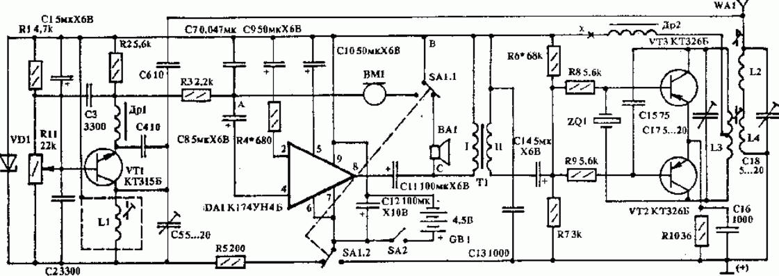
Encyclopedia of radio electronics and electrical engineering / Radio stations, transceivers This miniature transceiver is based on a transceiver circuit, the description of which is published in "RL" N2 / 92. It differs from the previous design in that the frequency of the transmitter master oscillator is stabilized by quartz, and this greatly simplifies tuning. The radio receiver is a conventional super-regenerative detector. Its only feature can be considered a variable resistor R11, which facilitates tuning and which, if desired, can be placed on the front of the transceiver. The sensitivity of the receiver is increased due to the use of the K174UN4B microcircuit in the LF amplifier, which, when powered by a 4,5 V battery, develops a power of 400 mW. The loudspeaker circuit is connected to the minus of the power source, which made it possible to simplify switching with the microphone circuit and use a paired button, which turns off the loudspeaker and receiver power in transmit mode, and connects the microphone and transmitter power in receive mode. In the diagram, SA1 is in the receiving position. The transmitter is assembled on two transistors and is a push-pull self-oscillator with quartz stabilization in the feedback circuit. A stable frequency allows, with a low transmitter power, to achieve a sufficiently large communication radius with the same type of radio station. It is necessary to tune the transceiver with ULF. After soldering the resistor R5, a milliammeter is connected to the SA2 circuit break. The idle current should not exceed 5 mA. When the screwdriver touches point A, noise should appear in the loudspeaker. If the amplifier is self-excited, then the resistance of the resistor R4 must be increased to 1,5 kOhm, but remember that the higher the resistor value, the lower the sensitivity of the amplifier. Further, by setting R5, the total current of the ULF and the superregenerative detector is measured. It is equal to 10 - 15 mA, while the sound in the form of hissing noise should be heard from the speaker. If there is no noise, it is necessary to move the slider of the resistor R11 from the upper (according to the diagram) position to the lower one. A loud, steady noise should appear, indicating that the super-regenerative detector is working well. Further tuning of the receiver is carried out only after tuning the transmitter and consists in adjusting the capacitance of the capacitor C1 (coarse tuning) and the inductance L1 (fine tuning) to the mode of the best reception of the transmitter signal. When setting up the transmitter, it is necessary to connect a milliammeter to the break in the "x" circuit and select the value of the resistance R6, such that the current is 40 - 50 mA. Then you need to connect a milliammeter at a measurement limit of 50 μA to the positive bus of the transmitter, and the other end of the device through a diode and a capacitor of 10 - 20 pF to the antenna. Adjustment of L3L4, C17, L2 and C18 is carried out until the maximum deviation of the instrument needle. Moreover, they are roughly tuned with capacities, or rather, with the cores of the circuits. The interlinear coil L3L4 should be no further than 3 mm from the middle position, since at its extreme points the generation may break due to the violation of the symmetry of the shoulders of transistors VT2 and VT3. When tuning with the extended antenna L2 and C 18 according to the maximum deviation of the arrow of the device, it is necessary to achieve complete matching of the antenna and transmitter. If, when the transmitter is turned on, the generation suddenly breaks, then this indicates an incorrect setting. In this case, it is necessary to select the operating modes of VT2 and VT3 again and carefully adjust L2, L3, L4, and if this does not help, then select transistors with closer parameters. rst1302 Resistors MLT-0,125 are used in the transceiver; capacitors K50-6. Transistor VT1 can be replaced with GT311Zh, KT312V, and transistors VT2, VT3 - with GT308V, P403. The conditions for replacing transistors are as follows: VT1 must have the highest possible gain at the cutoff frequency, and VT2 and VT3 must have the same current transfer coefficient. Loop coils L1 and L2 are wound on frames with a diameter of 5 mm. They have carbonyl iron tuning cores with a diameter of 3,5 mm and a height of 17 mm. The coils are enclosed in screens measuring 12x12x17 mm. Screen L1 is connected to the minus of the battery, and L2 is connected to the plus. Both coils are wound with PEV-0,5 mm wire and have 10 turns each. In the manufacture of coils, you can use the circuit from the IF channel of TVs. It was this frame that was used by the author in the manufacture of the L3L4 coil 25 mm long and 7,5 mm in diameter. On the board, it is located horizontally. Winding L3 and L4 is carried out with a step of 1 mm, the distance between the windings is 1 mm. L3 has 4 + 4 turns of PEV-0,5mm, L4 - 4 turns of the same wire. Coil L4 is located between the halves of the windings L3. Inductors Dr1 and Dr2 used factory, wound on resistors used in the IF paths of TVs. You can use any other loudspeaker with an impedance of 80m. Loudspeakers like 0,1GD-8 are suitable; 0,1 GD-6; 0.25GDSH-3. The transformer is wound on any small-sized magnetic circuit of the type Ш3 x 6 and contains 400 turns of PEV-0,23mm wire in the primary winding, and 200 turns of the same wire in the secondary. A small-sized capsule DEMSh1A is used as a microphone, but you can do without it if you use a loudspeaker with the inclusion of the latter according to the diagram in Fig. 2.
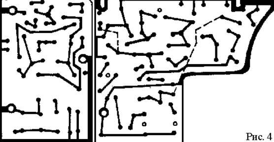
The antenna is telescopic, has a length of 105 mm. The author used one knee of a room television antenna. One flat battery type KBS-4.5V is used as a power source. You can replace it with four elements of the type A316, A336, A343. The boards are screwed to racks with M3 thread. All transmitter stands are connected to the front aluminum grille, which acts as a counterweight. The receiver stand, located near L1, is connected to the antenna using an aluminum bracket, which, in turn, is the antenna mounting element. The transmitter printed circuit board has holes for additional capacitances of trimmer capacitors C17 and C18. The microphone is fixed under the power supply, closed on all sides by a grounded aluminum shield and separated from the latter by thin foam rubber. The transceiver is designed for low-voltage power supply and therefore it is impossible to increase the supply voltage more than 7 - 8 V, as this will lead to overheating of the microcircuit and transistors VT2, VT3. The body of the transceiver is made of plastic and has a size of 270 x 70 x 40 mm. You can use two top covers from school pencil cases with the same dimensions. The installation is carried out on two printed circuit boards (Fig. 4): on the first - a transmitter, on the second - a bass amplifier and a receiver, between them is placed a screen made of a strip of aluminum measuring 68 x 38 mm.
The shield is connected to the positive battery bus. Author: A. Cherkashchenko
A New Way to Control and Manipulate Optical Signals
05.05.2024 Primium Seneca keyboard
05.05.2024 The world's tallest astronomical observatory opened
04.05.2024
▪ Professions disappearing and promising
▪ section of the site Palindromes. Article selection ▪ article Sprinkle ashes on your head. Popular expression ▪ Article Providing protection against electric shock from indirect contact ▪ article Experiments with carbohydrates. Chemical experience
Home page | Library | Articles | Website map | Site Reviews www.diagram.com.ua |


 Arabic
 Bengali
 Chinese
 English
 French
 German
 Hebrew
 Hindi
Hindi Italian
 Japanese
 Korean
 Malay
Malay Polish
 Portuguese
 Spanish
 Turkish
 Ukrainian
 Vietnamese


 Leave your comment on this article: