|
|


 Arabic
 Bengali
 Chinese
 English
 French
 German
 Hebrew
 Hindi
Hindi Italian
 Japanese
 Korean
 Malay
Malay Polish
 Portuguese
 Spanish
 Turkish
 Ukrainian
 Vietnamese
|
ENCYCLOPEDIA OF RADIO ELECTRONICS AND ELECTRICAL ENGINEERING Measuring device for ultrashortwave. Encyclopedia of radio electronics and electrical engineering
Encyclopedia of radio electronics and electrical engineering / Civil radio communications For those who are engaged in the design of amateur transceiver equipment, this device will be very useful. It allows you to evaluate the losses in the filters, the amplification of individual stages of the power amplifier line, the output power of self-oscillators, multipliers, mixers made on low-power transistors. This device (QRP-meter) measures low power levels in 50-ohm paths (for example, circuits) in a wide frequency range (1 ... 1296 MHz) and allows you to "see" and evaluate signal levels even at the output of passive diode mixers in the mode transmission (usually 0,5 ... 1 mW). The electrical circuit diagram of the device is shown in fig. 1. It is a conventional germanium diode rectifier with an input resistance of 50 ohms and has two measurement limits - 100 mW and 1 W.
In principle, it was possible to make the first limit more sensitive (for example, 10 mW), however, as practice has shown, in this case a separate scale of the measuring device is required, and this is not always convenient in operation. Therefore, it was decided to leave the measurement limit at 100 mW and use a measuring head with a relatively large scale. This allows you to confidently monitor input power levels in fractions of a milliwatt. Resistor R2 is used to equalize the frequency response of the device. To reduce the measurement error at the upper frequency limit (~ 1300 MHz), the load resistor (R1) 50 Ohm, it is best to use a microwave type (film) with dimensions of 10x7x7 mm, with strip leads and a mounting screw. In the extreme case (agreeing with a certain measurement error), it can be made up of four resistors of the MLT-0,25 / 0,5 type, 200 Ohms each, with leads shortened to 2 ... 3 mm, placing them on the reverse side of the input connector with a "star" around the center outlet. Trimmer resistors R4, R5 - any. Of the domestic diodes, it is best to use D1 as VD311, but D18 is also applicable. Of the imported ones, it is possible to use 1N34, 1N82. XP1 connector - bayonet type (SR-50-73F). The terminals of the rectifier elements (C1, C2, R2, VD1) are shortened to 2 ... 3 mm before soldering. At a frequency of 1296 MHz with an input power of 0,5 ... 1,0 W, the heating of the VD1 diode is felt and the readings of the device begin to "float". This must also be taken into account in order to avoid failure of the diode and to think over its cooling or to measure at this limit for a short time. The device is made in a case made of thin aluminum (Fig. 2). You can use foil fiberglass by simply soldering the walls of the case together. The assembly is carried out by surface mounting on a small board, put on the back of the connector. Due to the simplicity of the board, its drawing is not shown. The main thing is that the rectifier elements are in close proximity to the input connector.
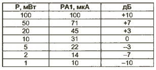
With serviceable parts, the setting is reduced to calibrating the scale. This is most easily done using an RF voltmeter (connected to the instrument's R1 resistor) and a GSS. However, not all generators provide output power levels at a load of 50 ohms greater than 5...20 mW. In this case, to apply the scale of the device, you can use the table below by setting the arrow to the appropriate division, equal to the maximum output power of the GSS. A device configured in this way (without claims for high accuracy) is quite a "workhorse". For example, when a QRP-meter is connected to the output of the G4-107 generator (OUT - 00 dB, mode - NG), it shows 20 mW in the entire frequency range of the generator (10 ... 400 MHz).
For loss estimation, filter bandwidth, etc. It is convenient to have a decibel scale. It can also be taken from the table. The scale of 1 W is almost the same (considering, of course, a multiplier of 10). If there is a signal generator for frequencies of 1000 ... 1300 MHz, it is possible to correct the frequency response of the device. To do this, within a small range (33 ... 82 ohms), R2 is selected according to the "sameness" of the readings at frequencies of 10 and 1000 MHz. Moreover, it should be remembered that an increase in R4 to a much greater extent reduces the readings at the upper frequency limit compared to the lower one. In general, as it turned out, the presence of R2 greatly reduces the SWR at the input at frequencies above 300 ... 400 MHz. As an example, let's evaluate the operation of the multiplier and the bandpass filter of the local oscillator of the 432/28 MHz transverter. We connect the QRP-meter to the first circuit of the band-pass filter (air strip lines), connected at the output of the transistor VT' of the 202/404 MHz doubler, through a thin (preferably with fluoroplastic insulation) cable 0,5 ... 0,6 m long with short stripped on 3 ... 5 mm leads (Fig. 3).
The connection can be made without soldering - using the "manual plugging" method, starting from the grounded output of the strip line. By adjusting the capacitor of this circuit, we achieve the maximum readings of the QRP-meter (the second circuit must be detuned). After making sure that the desired harmonic is selected (by any means), we move the connection points of the QRP-meter up the line, adjusting the capacitor. There comes a moment when the readings of the device practically do not grow, and the circuit setting begins to "get dull". Here it is reasonable to estimate the output power of the doubler. For low-power transistors, depending on the circuit, the magnitude of the connection between the circuits and the quality of the elements, it is in the range of 5 ... 15 mW (3 ... 6 dB of loss). At this stage, it is possible to adjust the filters, for example, by approaching or removing strip lines. Having achieved acceptable readings, we move on to the next cascade, and so on. Author: N.Myasnikov (UA3DJG), Ramenskoye, Moscow Region
The world's tallest astronomical observatory opened
04.05.2024 Controlling objects using air currents
04.05.2024 Purebred dogs get sick no more often than purebred dogs
03.05.2024
▪ Serotonin does not affect the development of depression ▪ Reconstructed the navel of the earth ▪ Acoustic waves for the treatment of muscle injuries ▪ Canon Dual Lens for VR Content Capturing
▪ section of the site Normative documentation on labor protection. Article selection ▪ article Invitation to execution. Popular expression ▪ article Who is John Calvin? Detailed answer ▪ article Kokorysh. Legends, cultivation, methods of application ▪ article Ink powders. Simple recipes and tips
Home page | Library | Articles | Website map | Site Reviews
www.diagram.com.ua |


 Leave your comment on this article: