|
|


 Arabic
 Bengali
 Chinese
 English
 French
 German
 Hebrew
 Hindi
Hindi Italian
 Japanese
 Korean
 Malay
Malay Polish
 Portuguese
 Spanish
 Turkish
 Ukrainian
 Vietnamese
|
ENCYCLOPEDIA OF RADIO ELECTRONICS AND ELECTRICAL ENGINEERING Adjustable 144 MHz antenna amplifier. Encyclopedia of radio electronics and electrical engineering
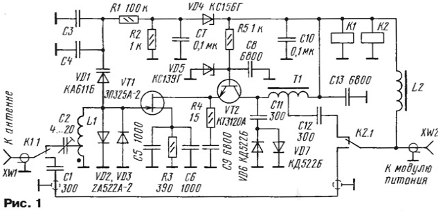
Encyclopedia of radio electronics and electrical engineering / Civil radio communications An antenna amplifier based on a gallium arsenide field-effect transistor will help to significantly improve the quality of receiving signals in the 2-meter range [1, 2]. But if there are radiotelephones or trunk communication systems nearby, then its effectiveness is often sharply reduced due to the occurrence of crosstalk or clogging the weak signal of the correspondent with a strong interference signal. It is possible to weaken the action of interfering signals by narrowing the bandwidth of the amplifier. However, the problem of amplifier tuning stability immediately arises here. When placed outdoors due to temperature changes, it can be completely broken. The way out of this situation can be the use of an adjustable amplifier, the tuning frequency of which can be changed within small limits remotely from the room where the receiving equipment is located. In this case, its adjustment can be carried out to the maximum sensitivity by ear at any time. The scheme of the adjustable antenna amplifier for the 144 MHz range is shown in fig. 1. It contains an input circuit, which is formed by an inductor L1 and capacitances of a varicap VD1, diodes VD2, VD3, a field effect transistor VT1 and mounting. Frequency tuning of the circuit is carried out by applying voltage to the varicap.
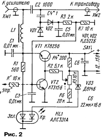
The amplifier itself is assembled according to a cascode circuit on transistors VT1 and VT2, while an amplifying stage is assembled on a transistor VT2 according to a common base circuit. This reduces the effect of the drain-gate FET parasitic capacitance on the performance of the amplifier. At the same time, the transistor VT2, together with the zener diode VD5, performs the function of a voltage regulator for the cascade on VT1. Autotransformer T1 matches the high output impedance of the stage to the low impedance of the drop cable. Diodes VD2, VD3, VD6 and VD7 protect the amplifier from powerful transmitter signals. The R4C9 chain improves stability. Power is supplied to the amplifier through inductor L2. The amplifier is turned on by supplying voltage through the drop cable. If there is no voltage, the antenna amplifier is turned off and the antenna is connected to the transceiver through capacitor C1 and relay contacts K1- and K2. This condition is typical for transmission mode or when the amplifier is turned off. When the supply voltage is applied, the relays K1 and K2 will work and connect the amplifier. For frequency tuning, the supply voltage is changed from 6 to 9 V, the relays remain on, and a voltage of approximately 1 to 4 V is supplied to the VD0,4 varicap (through the VD4,4 zener diode). This ensures that the input circuit is tuned in frequency (in the author's version 138 to 157 MHz). The gain was 24 dB. If you replace the autotransformer T1 with a 120 ohm resistor (capacitor C11 is connected to the collector VT2), the gain decreases to 18 dB. The maximum current drawn by the amplifier is 140mA. The amplifier is powered by a drop cable through a special device, the circuit of which is shown in fig. 2. On the transistor VT1 and the zener diode VD3, an adjustable parametric voltage regulator is assembled, on VT2 - an electronic key, and on diodes VD1 and VD2 - an RF voltage rectifier. /Two-color LED HL1 provides an indication of the operating modes of the device.
When the power is off (switch SA1 is open), no voltage is supplied to the amplifier. When SA1 is closed, a voltage is supplied to the amplifier, which can be changed by resistor R5 (and thereby adjust the tuning frequency of the amplifier). In this case, both LEDs will be lit, resulting in a yellow glow. When the transceiver switches to transmission, its signal is rectified by the diodes VD1, VD2 and the transistor VT2 opens. In this case, the voltage at the base of the transistor VT1 will decrease to fractions of a volt, no voltage will be supplied to the antenna amplifier and it will turn off. The green LED will turn off and only red will light, indicating transmission mode. When working with the transceiver in SSB mode, to turn off the antenna amplifier during transmission to the "Control" input. A few volts must be applied. In the amplifier, you can use: transistor VT1 - AP325A-2, VT2 - KT382A, varicap VD1 - KA610B. The tuned capacitor C2 is KT4-25, the rest it is desirable to use leadless ones (K10-17v) or with leads, but of a minimum length, and small-sized ceramic ones. Resistors - MLT, S2-33. Coil L1 is wound with a wire with a diameter of 1 mm on a frame of 8 mm and contains 8,5 turns with a tap from the 0,5th turn, the winding length is 12 mm. The author used a bare copper wire (the central core of the RF cable), while the bandwidth of the amplifier was 1,2 MHz. If you use a silver-plated wire, then the bandwidth can be slightly reduced. The autotransformer T1 is wound on a K5x1 x1,5 ring made of ferrite with a permeability of 2000 with a PEV-2 0,2 wire and contains 2x10 turns (twice folded wire). Inductor L2 - DM-0,4 with an inductance of 20 μH. Relays K1 and K2 - REK43 with a response voltage of 5,5 ... 6 V and a winding resistance of 125 ohms. Setting up the amplifier comes down to setting the tuning range by selecting the number of turns of the L1 coil and moving apart its turns. The bandwidth and matching is set by the capacitor C2 or by changing the location of the tap from L1. In the power module, capacitor C4 is selected so that the device switches stably. By selecting the resistor R4, they ensure that a current of approximately 3 mA flows through the zener diode VD15. Author: I. Nechaev (UA3WIA), Kursk
Machine for thinning flowers in gardens
02.05.2024 Advanced Infrared Microscope
02.05.2024 Air trap for insects
01.05.2024
▪ Achieved data transfer rate of 43 terabits per second ▪ Light bulb with vacuum cleaner ▪ Scientists succeeded in synthesizing a decanter ▪ Butter is recognized as a harmful product
▪ section of the site Mobile communications. Article selection ▪ article Catherine II. Famous aphorisms ▪ article Soya cultural. Legends, cultivation, methods of application ▪ article Low power transmitter. Encyclopedia of radio electronics and electrical engineering ▪ article Laboratory transformer. Encyclopedia of radio electronics and electrical engineering
Home page | Library | Articles | Website map | Site Reviews
www.diagram.com.ua |

 Leave your comment on this article: