|
|


 Arabic
 Bengali
 Chinese
 English
 French
 German
 Hebrew
 Hindi
Hindi Italian
 Japanese
 Korean
 Malay
Malay Polish
 Portuguese
 Spanish
 Turkish
 Ukrainian
 Vietnamese
|
ENCYCLOPEDIA OF RADIO ELECTRONICS AND ELECTRICAL ENGINEERING Feeder antenna effect. Encyclopedia of radio electronics and electrical engineering
Encyclopedia of radio electronics and electrical engineering / Civil radio communications The normal operation of the antenna-feeder path largely determines the effectiveness of an amateur radio station as a whole. The effect discussed in this article can significantly reduce it, since it manifests itself in most practical antenna designs (including factory-made ones). The first part of the article reveals the causes of the feeder antenna effect and its influence on the operation of the antenna-feeder path. In the second part, practical recommendations will be given to eliminate this influence. Almost every shortwave is well aware of the situation when the transmission work interfered with the electronic equipment in the house - the neon light glows when brought to the body of the switched on transmitter, and the reception is accompanied by strong interference of local origin. These are the most striking manifestations of the long-familiar, but relatively little-studied feeder antenna effect, the essence and features of which are described in the article. The essence and causes of the antenna effect of the feeder It is customary to call the antenna effect the phenomenon of radiation or reception of radio waves by objects not intended for this. The feed line should only be used to transmit high frequency energy from a transmitter to an antenna or from an antenna to a receiver. Consideration of the causes of the feeder antenna effect (AEF) will begin with the transmission mode. As you know, the electromagnetic field emitted by the antenna is created by alternating currents flowing through its constituent conductors. Almost always the antenna is not in free space. In the immediate vicinity of it (for example, within the wavelength a) there can be many objects. These are wires of power supply, broadcasting and communication lines, conductive masts, supports and guys, pipes, rigging, fittings, bodies and fuselages of vehicles, roofs and walls of buildings, the operator's body and the surface of the earth. If currents somehow arise in the objects of the environment (induced, for example, by the near field of the antenna), then the radiation field created by these currents will add up to the field from the antenna currents. The antenna together with the environment will be called the antenna system (AS). Under these conditions, the characteristics of the speakers may differ greatly from the calculated characteristics of the antenna itself. In order for the characteristics of the speakers to be less dependent on the environment, they try to raise the antenna higher, install it further from conductive structures, make non-metallic masts, braces. One of the nearest and fundamentally unremovable objects of the antenna environment is the feeder that feeds it. The simplest feeder is an open two-wire line. In the ideal case, the instantaneous values of currents in the wires of the line in any section of the feeder and at any time are the same in magnitude and opposite in direction, i.e., the sum of the currents of both wires of the feeder in any section is equal to zero. We will call such currents antiphase. An open two-wire line will radiate even under this condition, the reason for this is the finite distance d between the wires of the line. A vertical line radiates in the horizontal plane vertically polarized waves with maxima in the plane of the line and horizontally polarized waves with maxima perpendicular to this plane. The radiation field is proportional to the ratio d/X. The radiation of a two-wire line is minimal at a matched line load and noticeably increases with a mismatch, when standing current waves appear. The described phenomenon (under the condition of strictly antiphase currents in the feeder wire system) is called the antenna effect of the feeder of the 2nd kind (AEF-2) [1]. In practice, it manifests itself very weakly. For example, at a frequency of 145 MHz, a line from a KATB (or KATP) television cable with a length of a / 2 at d \u10d 50 mm radiates a field about XNUMX times weaker due to this effect than a half-wave loop vibrator connected to this line. There are many reasons why the sum of the currents of all wires in the cross section of the feeder line can be different from zero. The vector diagram (Fig. 1) shows that with an arbitrary phase and amplitude difference of the currents I1 and I2 in individual wires, these currents can be represented as the sum of antiphase I1n = I2n and in-phase I1c =l2c components (the latter are sometimes called single-cycle). The fields created by the common-mode currents of different wires are not compensated (as anti-phase), but summed up. If the length of the feeder is comparable to X, then their sum can create a large additional radiation. This phenomenon is called the antenna effect of the feeder of the 1st kind (AEF-1) [1]. It is noticeably more serious than AEF-2. which will be discussed below.
Since AEF of the 1st kind (hereinafter simply AEF) is associated with common-mode currents, the problem of determining its causes can be reduced to finding the causes of the appearance of common-mode currents of the feeder line in the transmission mode (in the receive mode, such currents always arise under the influence of external electromagnetic fields). Consider a horizontal dipole antenna with a two-wire feeder without taking into account the "ground". We will assume that the AU consists only of an antenna and a feeder. The radiation field of the AS at each point in space is the vector sum of the fields created by the currents of all AS conductors. The total field at each point depends on the distribution of currents along the conductors of the system. This distribution at a given frequency is uniquely determined by the shape, size and placement of the AC wires. as well as the method of stimulation. Sufficiently obvious considerations lead to the conclusion (confirmed by calculation and practice) that with the geometric symmetry of the AU and symmetrical (strictly antiphase) excitation, the distribution of currents will also be symmetrical both along the antenna wires and along the feeder wires. In this case, the sum of the common-mode currents of all feeder wires will be equal to zero.
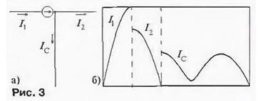
An example of such a case is shown in the model in Fig. 2a. The currents of the wires of a symmetrical feeder are the same in amplitude and antiphase, this is determined by the symmetry of the arms of the vibrator antenna and the symmetrical location of the symmetrical feeder relative to these arms, as well as the symmetrical connection of the generator to the beginning of the feeder line. Any of the following reasons can lead to the appearance of common-mode feeder currents: antenna asymmetry (geometrical asymmetry of the arms, power not in the middle, Fig. 2, b): feeder asymmetry (different diameters or lengths of wires, Fig. 2, c); asymmetry of the SS as a whole (asymmetric relative position of the antenna and feeder, Fig. 2, d). When taking into account the "earth", the geometric asymmetry of the AS relative to the "earth" (Fig. 2, e) and the electrical asymmetry of the source relative to the "ground" (Z1-Z2. Fig. 2, f) will be added here If in the previous situation complete symmetry is possible in principle, then when a symmetrical antenna is powered by a coaxial (fundamentally asymmetric) feeder without taking special measures, AEF-1 is simply inevitable, although such a feeder is free from AEF-2. A feature of the coaxial line is that. that at high radio frequencies it can be considered not as a two-wire, but as a three-wire line. The currents on the inner and outer surfaces of the cable sheath may differ due to the skin effect. To analyze common-mode currents on the model, you can represent the outer surface of the cable sheath with one wire, and connect the generator directly to the antenna. In the case when the central conductor of the cable is connected to one arm of a symmetrical antenna, and the braid to the other (model - Fig. 3, a), then even with a geometrically symmetrical location of the cable relative to the antenna, AEF will occur in the speaker. The reason is the electrical asymmetry of connecting an equivalent source to a geometrically symmetrical speaker (the source is supposed to be a point source and turned on exactly in the center of the antenna, but on the left is one antenna arm, and on the right is the other plus the outer surface of the cable sheath!). In this case, the current distribution strongly depends on the electrical length of the outer surface of the cable sheath (due to external insulation, it is approximately 1% larger than the geometrical length), with a resonant length (an integer number of half-waves, taking into account the ground length for the grounded lower end, or an integer number of half-waves plus a / 4 for the ungrounded end of the cable, as in our case), the maximum amplitude of the common-mode current lc of the cable is maximum and can reach 43% of the maximum amplitude of the current I of the left arm of the antenna (Fig. 3,b).
In this example, it is convenient to show a simplified "mechanism" of inducing currents along the outer surface of the braid, which will help to more clearly present the physical processes leading to the AEF. One of the reasons for the common mode current is obvious: it is an equivalent excitation source, to one of the terminals of which an outer conductor is connected. However, this conductor is also in the near field of the antenna arms, the currents in which are not the same. As a result, there is another reason for common-mode currents: asymmetric, and therefore uncompensated at the location of the feeder, the near field of the antenna itself. Such an idea is, of course, very primitive, but sometimes in the practice of combating AEF, for some reason, this second reason is not taken into account at all. Significantly asymmetric with respect to the "ground" (or roof) are vertically polarized antennas located at a low height. Even if we provide the formal relative symmetry of the antenna and the feeder (vertical dipole when fed from the side). AEF is inevitable. Thus, in transmission operation, feeder common-mode currents can occur for any of the following main reasons:
In the receiving mode, under the action of external electromagnetic fields on the feeder line, both antiphase and common-mode currents can occur in its wires. The former arise in open two-wire lines and directly affect the input of the receiver (AEF of the 2nd kind). Common mode currents occur in any feeder line. By virtue of the principle of reciprocity, the effect of these currents on the input of the receiver (AEF of the 1st kind) is the stronger, the greater the relative intensity of the common-mode currents of the feeder of this AS in the transmission mode. Only anti-phase currents of the feeder can act directly on a correctly made input of the receiver. The "mechanism" for converting common mode currents in the receive mode into antiphase currents is similar to that described above for a coaxial feeder in the transmit mode. One of the ways is to connect the outer surface of the braid with the inner one at the point of connection of the antenna, and the second - through the antenna, by means of the common-mode near-field currents, which are asymmetric for different arms of the antenna, with an asymmetric speaker. The characteristics of the AU, taking into account the feeder as part of it, differ from the calculated characteristics of the antenna without taking into account the influence of the feeder. Thus. AEF is not only the reception or transmission directly by the feeder, so the concept can be expanded. AEF in a broad sense is the influence of the feeder on the characteristics of the antenna system (both during reception and transmission). Let's consider this influence in more detail. Manifestations of the antenna effect of the feeder The most striking manifestations of AEF were noted above. Let us consider these and possible other significant manifestations of AEF in more detail. As examples, we take a horizontal half-wave vibrator and the well-known vertical antenna GP with a height of λ/4 with three counterweights of the same length, installed at an angle of 135° to the radiator. The input impedance of such an antenna in free space and without taking into account the influence of the feeder is purely active and is about 50 ohms. On fig. 4 shows the radiation pattern (DN) in the vertical plane and the distribution of currents along the wires of the pin (I1) and counterweights (I2 - I4) for this case. All characteristics given here are obtained using computer simulations without taking into account losses.
During transmission, the following manifestations of ADF may occur. 1. Appearance of AS radiation with non-fundamental polarization. If the main polarization of the antenna is vertical and the feeder is not vertical, the feeder radiation will appear with a horizontal component. If the main polarization of the antenna is horizontal and the feeder is not horizontal, the feeder radiation will appear with a vertical component. Example - DN in the vertical plane fig. 5 for a horizontal dipole. The vertical component of the field En due to the AEF is about 30% of the useful horizontal En. And this is a very undesirable effect, for example, for television reception.
2. Change in RP with the main polarization. The radiation of the feeder with the main polarization can lead to a significant change in the main RP (for example, for vertical antennas in the vertical plane): the directivity factor changes in the main direction (it can be either a decrease or an increase), unwanted lobes appear in other directions. An example is fig. 6 for GP antenna with 9λ/4 ungrounded cable length. If the cable with the main polarization does not radiate, then the pattern may change as a result of violation of the symmetry of the excitation (Fig. 7 for Ep, a horizontal dipole) 3 Change the complex input resistance. For the GP antenna, depending on the length of the coaxial feeder, the active component R of the complex resistance at the excitation points Z = R + jX can vary from 42 to 100 ohms. and the reactive component X is from -40 to +17 ohms. 4. A change in the input resistance is associated with a change in the standing wave ratio (SWR) in the feeder line. On fig. Figure 8 shows the dependences of the SWR for the GP antenna at λ=10.9 m: 1 - with a "normal" cable connection to the antenna; 2 - with perfect "isolation" of the outer surface of the braid at the point of connection to the antenna. As can be seen from the graphs, the SWR in both cases depends on the length of the feeder, which should not occur in the absence of common-mode currents (AEF) and losses in the feeder [2]. We note here that it is the common-mode currents that lead to a change in SWR (through Z), but not vice versa! The dependence of AEF-2 on SWR has a different "mechanism".
5. Poor SWR means the presence of a significant proportion of standing waves in the feeder currents that are not involved in the transfer of RF energy. In a real cable, losses increase, as a result, the efficiency of the antenna-feeder system decreases. Common-mode currents themselves also lead to additional losses of energy supplied to the AC. 6. Deterioration of DN and SWR. a decrease in efficiency reduces the energy potential of the radio link. The range of reliable reception decreases, and in order to achieve the calculated communication quality, it is required to increase the power. And this is an additional cost of energy. At the same time, the problems on points 7-9 are exacerbated. 7. Changing the pattern leads to the appearance of radiation in unforeseen directions, which can create intense interference or field levels that are unacceptable according to sanitary standards. 8. If the feeder is located near other lines, for example, power or telephone lines, the presence of an inductive connection with them in the presence of AEF can lead to serious difficulties in ensuring the joint operation of the radio station with other electronic means (strong mutual interference during transmission and reception). 9. Near the feeder of the transmitting device, a noticeable electromagnetic field may arise, comparable to the fields near the active parts of the AU. All. with regard to changes in the general characteristics of the transmitting AS. equally applies to receiving speakers (DN. input impedance. SWR. Efficiency) External sources of interference with non-primary polarization or in the zone of additional lobes of DN. or near the feeder, if there is an AEF, they will create an additional interference background during reception. We note some general features of the manifestation of AEF: 1. AEF manifests itself more strongly with resonant dimensions of the feeder and weaker - with non-resonant dimensions. 2. The nature of the change in RP in the presence of AEF depends on the length of the feeder. The longer the vertical feeder, the more indented the DN becomes in the vertical plane. 3. The amplification of the AS in the main direction in the presence of the AEF can be both greater and less than without taking into account the AEF. 4. The AEF manifests itself the stronger, the stronger the near field of the antenna is the feeder. In this sense, the considered GP antenna is one of the most vulnerable. 5. For vibrator (dipole) antennas, AEF is more pronounced than for loop ones. 6. For vertically polarized antennas, AEF appears more often and stronger than for horizontally polarized antennas. 7. The influence of the feeder on the characteristics of the AU is the stronger, the smaller the size of the antenna and the lower its efficiency. ADF is very dangerous for electrically small antennas. 8. AEF is especially dangerous for highly directed and. in particular direction finding antennas. 9. The manifestation of AEF in receiving AS is no less, but even more serious than in transmitting. It was for receiving speakers that this problem first arose. Literature
Authors: Anatoly Grechikhin (UA3TZ), Dmitry Proskuryakov
A New Way to Control and Manipulate Optical Signals
05.05.2024 Primium Seneca keyboard
05.05.2024 The world's tallest astronomical observatory opened
04.05.2024
▪ Japan will no longer need drivers in ten years ▪ OmniVision OV12890 sensor with 1,55 micron pixels ▪ The brain predicts the future ▪ Weather forecast based on GIS ▪ These children are in our livers
▪ site section Computer devices. Article selection ▪ article Sun of Austerlitz. Popular expression ▪ article What is the longest subway? Detailed answer ▪ article Common honeysuckle. Legends, cultivation, methods of application
Home page | Library | Articles | Website map | Site Reviews
www.diagram.com.ua |


 Leave your comment on this article: