|
|


 Arabic
 Bengali
 Chinese
 English
 French
 German
 Hebrew
 Hindi
Hindi Italian
 Japanese
 Korean
 Malay
Malay Polish
 Portuguese
 Spanish
 Turkish
 Ukrainian
 Vietnamese
|
ENCYCLOPEDIA OF RADIO ELECTRONICS AND ELECTRICAL ENGINEERING Receiver-controller. Encyclopedia of radio electronics and electrical engineering
Encyclopedia of radio electronics and electrical engineering / radio reception Success in competitions of radio-controlled models largely depends on the accuracy of the transmitters of the executive teams. You can control the operation of the transmitting equipment using a simple receiver, in the phone of which the sounds of the frequencies of the modulating commands are clearly audible. Watching the flight of the model, one can judge the quality of the command execution. The receiver, in addition, will indicate the presence of "ether" interference that can disrupt the normal operation of the receiving equipment of the model. For several years, such a "controller" receiver was used by young technicians of the Moscow City Palace of Pioneers and Schoolchildren to control the operation of radio equipment at model aircraft competitions. The sensitivity of the receiver is not worse than 10 μV, the range of received frequencies is 26,0-32,0 MHz. Reception is carried out on a piece of insulated wire about a meter long. The receiver is powered by one battery type KBS-L-0,50. The weight of the receiver without a power supply is about 60 g, dimensions are 110X24X17 mm. The circuit diagram of the receiver is shown in fig. 1. This is a super-regenerative detector based on transistor T1 with a three-stage low-frequency amplifier based on transistors T2, T3 and T4. The setting of the input circuit L1C5, included in the collector circuit of the transistor Hz, is carried out by the capacitor C5, and its adjustment to the selected frequency range is carried out by the core of the coil L1. The received signal is amplified and detected by the transistor T1. The low-frequency signal selected on the resistor R3 through the filter cell R4C7 and the capacitor C8 is fed to the input of the low-frequency amplifier.
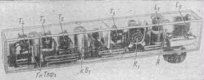
The low-frequency amplifier uses a direct connection between the transistors of the first and second stages and temperature compensation, which operates automatically over a wide temperature range. The signal at the input of the amplifier (points a and b), after amplification by the transistor T2, is separated at the resistor R6 and fed directly to the base of the transistor T3. The load of this stage is the resistor R7, from which the signal is fed through the capacitor C9 to the base of the transistor T4 for further amplification. Resistors R8 and R9 form a divider, from which the necessary bias voltage for transistor T4 is removed. The bias voltage for the transistor T2 is formed across the resistor R7 and is fed through the resistor R5 to its base. The same voltage stabilizes the operation mode of the transistor T2 when the temperature changes. Since the collector of transistor T2 and the base of transistor T3 are connected directly, the bias of transistor T3 depends on the voltage at the collector of transistor T2 and, therefore, on its mode. Since the bias voltage of transistor T2 is removed from the emitter of transistor T3, mutual stabilization of the modes of both transistors occurs. So, for example, with an increase in temperature, the collector current of transistor T2 increases, which reduces the voltage on its collector and on the base of transistor T3. In this case, the collector current of the transistor Tu and the voltage at its emitter become smaller. This causes a decrease in the bias voltage at the base of transistor T2, which leads to a decrease in its collector current. Details. Coil L1 is wound on a frame with a diameter of 8 mm (from the FPC of the Rubin TV) and has 10 turns of PEL-1 0,5 wire. Coil core type SCR with a diameter of 6 mm. Capacitor C5 - tuning with an air dielectric with a maximum capacitance of 20-25 pF. The inductor Dr1 is wound on the body of a MLT-0,5 type resistor (with a resistance of more than 1,0 MΩ) and contains 200 turns of PEL-1 0,1 wire. Its inductance is about 40 uH. Resistors and capacitors are small-sized: the dimensions of the receiver depend on them. Telephone Tlf1 - telephone capsule from the hearing aid "Crystal". It can be replaced by an electromagnetic telephone with a coil resistance of 60-150 ohms. Transistor P416B can be replaced by transistors of types P401-P403, P422, P423, GT313 with a gain Vst within 30-100. Any low-frequency transistors with a gain Vst of at least 40 can be used in a low-frequency amplifier. The appearance of the receiver, designed to be carried in a jacket pocket, is shown in Fig. 2. The case is made of 1,5mm transparent organic glass. The sockets and plugs of the power connector are used to connect the antenna, telephone and battery.
Establishing the receiver should begin with a low-frequency amplifier. To do this, a sound generator is connected to points a and b (Fig. 1), and a tube voltmeter is connected to points c and d. A signal with a voltage of 2-3 mV, a frequency of 1000 Hz is supplied from the sound generator to the input of the amplifier, and by selecting the resistances of resistors R6 and R8, the greatest deviation of the voltmeter needle is achieved. In the absence of devices, you can adjust the amplifier by the highest volume of the signal from the pickup connected to points a and b. The establishment of a super-regenerative cascade consists in the selection of the resistance of the resistor R1. Instead, a variable resistor of 47-51 kΩ is temporarily soldered in and by changing its resistance, "super" noise appears in the phones. After that, you can try to tune the receiver to one of the amateur stations operating in the 28,0-29,7 MHz band. When finely tuned to the station, the "super" noise should disappear. Then, once again, select the resistance of the variable resistor and replace it with a constant of the same rating (in Fig. 2 R1 is a variable resistor). The boundaries of the range of received frequencies are set by the core of the L1 coil according to the standard signal generator or the transmitter signals for radio-controlled models. Author: N. Putyatin; Publication: N. Bolshakov, rf.atnn.ru
Artificial leather for touch emulation
15.04.2024 Petgugu Global cat litter
15.04.2024 The attractiveness of caring men
14.04.2024
▪ Estimate of human height over 2000 years ▪ Platform MediaTek LinkIt Smart 7688 ▪ Biofuel at a price of 1 euro per liter ▪ Climate change has affected the taste of beer ▪ The baby's cells stay in the mother's brain
▪ section of the site for the Musician. Selection of articles ▪ article The human genome. History and essence of scientific discovery ▪ article What kind of mask were grumpy women forced to wear centuries ago in England? Detailed answer ▪ article Carrying out subbotnik. Standard instruction on labor protection ▪ article Car socket 220 volts 400 watts. Encyclopedia of radio electronics and electrical engineering
Home page | Library | Articles | Website map | Site Reviews
www.diagram.com.ua |

 Leave your comment on this article: