|
|


 Arabic
 Bengali
 Chinese
 English
 French
 German
 Hebrew
 Hindi
Hindi Italian
 Japanese
 Korean
 Malay
Malay Polish
 Portuguese
 Spanish
 Turkish
 Ukrainian
 Vietnamese
|
ENCYCLOPEDIA OF RADIO ELECTRONICS AND ELECTRICAL ENGINEERING 28 MHz direct conversion receiver for space communications. Encyclopedia of radio electronics and electrical engineering
Encyclopedia of radio electronics and electrical engineering / radio reception The receiver described in this article is designed to receive CW and SSB signals from amateur radio stations in the 29.3 ... 29.6 MHz section. As you know, this section of the 10-meter range is recommended for amateur communications through repeaters installed on artificial Earth satellites (channel for receiving signals from the satellite). The characteristics of the receiver make it possible to use it with simple antennas for organizing amateur communications through educational and experimental IC3 located in circular orbits with an altitude of up to 2000 km and having on-board repeaters with an output power of about 1 W. Technical specifications Received frequency range, MHz ....... 29,3 ... 29,6
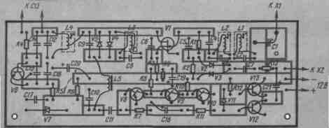
The circuit diagram of the receiver is shown in Fig.1. It contains an RF amplifier, a diode mixer, a local oscillator and a bass amplifier.
The signal from the antenna through the matching coupling capacitor C1 is fed to a two-circuit bandpass filter L1C2L2C3 with a bandwidth of about 300 kHz, and then amplified by the transistor V1. The collector circuit of this transistor includes an L3C8 circuit tuned to a frequency of 29,45 MHz. The gain of the high frequency amplifier is only slightly above unity. The point of using such an amplifier is to compensate for losses in the bandpass filter and to weaken the passage of the local oscillator signal to the antenna. The receiver mixer is made on diodes V4 and V5 connected in anti-parallel. The received signal is fed to it ("L3C8 circuit") and the local oscillator voltage (from part of the L4 coil). In accordance with the principle of operation of the mixer, the local oscillator frequency is set twice as low as the frequency of the received signal, i.e. 14,6 ... 14,8 MHz. The receiver local oscillator is made on the transistor V6 according to the capacitive three-point scheme, which provides increased frequency stability due to the relatively large capacitance of the capacitors C15 and C16, connected in parallel with the transistor junctions. A change in the junction capacitances in this case has little effect on the generation frequency. The supply voltage of the local oscillator is stabilized by the Zener diode V7. The low-frequency signal, isolated by the L5C9C10 low-pass filter with a cutoff frequency of 2,8 kHz, is fed to a three-stage low-frequency amplifier on transistors V8-V10, V12. V13. To improve temperature stability, the amplifier is assembled on silicon transistors. All three stages through resistors R7 and R11 are covered by negative DC feedback. The final power amplifier is made according to the scheme of a push-pull emitter follower on transistors V12, V13 of different structures. Diode V11 is used to create a small initial bias of the output transistors, which reduces the distortion type "step". To the output of the receiver, you can connect telephones with an impedance of at least 70 ... 100 Ohms or a loudspeaker for a city broadcasting network. Low-resistance drivers can be connected via a matching transformer with a winding ratio of approximately 5:1. There is no provision for adjusting the gain of the low-frequency signal, since the AGC system operates quite effectively. The AGC circuit contains a rectifier (diodes V2, V3) and a smoothing RC circuit (R2C5). The signal to the AGC rectifier comes from the output of the receiver through the R13C7 chain. When powered by a battery (9 V), the voltage at the zener diode V7 is lower than the operating voltage and the current consumption decreases sharply. If the receiver is supposed to be powered only by batteries, the V7 zener diode can be omitted. Measures have been taken in the receiver to increase the sensitivity and reduce the level of intrinsic noise. A low-noise silicon transistor KT208 is installed at the input of the bass amplifier. The mixer uses low-noise diodes with a Schottky barrier KD514A. The entire signal path from the mixer input to the base of the input transistor of the low-frequency amplifier is impedance-matched, which ensures low signal power losses. The mixer impedance, the characteristic impedance of the low-pass filter, and the input impedance of the low-pass amplifier are equal to each other and are approximately 2 kΩ. The receiver can be made without an RF amplifier, but this will lead to a decrease in the selectivity of the preselector. In addition, of course, the AGC system will not work. The input circuit in this case is performed according to the circuit shown in Fig. 2.
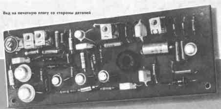
The signal received by the antenna is filtered by the L-shaped link of the L6C1L3C2 bandpass filter and immediately goes to the mixer. The filter bandwidth is 2...3 MHz. Compared to a single input loop, the filter provides significantly better rejection of out-of-band signals and lower passband loss. Thanks to the autotransformer connection of the longitudinal (L6C1) and transverse (L3C2) branches of the filter, the antenna resistance (3 Ohm) is transformed through the outlet of the coil L75 and is consistent with the input impedance of the mixer (2 kOhm). The sensitivity of the receiver without an RF amplifier with an input circuit built according to the scheme of fig. 1 reaches 0,3 ... 0,4 μV. Design. The receiver is mounted on a printed circuit board measuring 140x50 mm. The color in the figure highlights the tracks from which the foil was removed.
Ceramic capacitors are used in the high-frequency circuits of the receiver. Capacitor C13 is a small-sized trimmer with an air dielectric, containing one movable and one or two fixed plates. Electrolytic capacitors - K53-1, the rest - KLS. Resistors can be of any type. Loop coils L1-L4 and L6 are wound on self-made organic glass frames. The frame sketch is shown in fig. 4. For the manufacture of a frame from a 6 mm thick organic glass plate, a workpiece is cut off with dimensions of 9X13 mm. A hole is drilled in it and an M4 thread is cut. Excess material is removed with a jigsaw or hacksaw, and then the working part of the frame is shaped with a file, close to cylindrical. The coils are tuned with SCR-4 cores taken from SB-12a armor cores. Each core should be sawn in half and sawed through a slot on the second half with a jigsaw, thus making two builders. Their length will be about 5 mm.
The winding data of the coils are shown in the table. Coils are wound coil by coil. Coil L5 is wound on a ring core made of M1500NM ferrite (size K12X8X6).
You can use other cores with an outer diameter of 10 to 20 mm, adjusting the number of turns accordingly. It should be inversely proportional to the square root of the magnetic permeability. For example, if M3000NM ferrite is used, the number of turns should be reduced to 270. The ring diameter affects the inductance less, but when using a larger ring, the number of turns should be slightly reduced. The KP303E transistor in the receiver can be replaced with KP303D or KP303G. Diodes V2, V3 - any silicon. In a mixer, KD503A can be used with a slightly worse result. KD503B or KDS523. In the local oscillator, you can use transistors KT312 and KT315 with any letter indices. The bass amplifier can also be made on germanium low-frequency transistors P27A, P28 (V8), MP39-MP42 (V9, V10 and V13), MP9-MP11, MP37 (V12). In this case, thermal stability will only slightly deteriorate. To obtain sufficient low-frequency gain, the coefficient h21e of transistors V8-V10 must be at least 60 ... 80. In this low-frequency amplifier, high-frequency transistors should not be used, since in this case intractable self-excitation is often observed at frequencies of the order of tens to hundreds of kilohertz. Diode V11 - any low-power germanium. The design of the receiver can be anything, it is only important to place the capacitor C13 in close proximity to the local oscillator circuit. The capacitor is connected to the circuit with short rigid conductors.
Setting up the receiver begins with checking the modes of the transistors. The voltage at the emitters of transistors V12 and V13 should be equal to half the supply voltage. This is achieved by selecting resistors R7 and R11. The bass amplifier usually does not require any other adjustment. The currents of transistors VI, V6 are set by resistors R3 and R4. The local oscillator frequency is set by the core of the coil L4. The frequency is controlled by a resonant wavemeter or a graduated KB receiver. Then you should check the sensitivity of the receiver without an RF amplifier by temporarily disconnecting the drain terminal of transistor V1 from coil L3. If you connect an external antenna to the upper output of the L3 coil through a coupling capacitor with a capacitance of 3 ... 5 pF, you should hear "air noise" and you can receive signals from amateur stations. The L3C8 circuit is then adjusted to the maximum reception volume. To achieve maximum sensitivity, you should select the local oscillator voltage on the mixer diodes by adjusting the position of the L4 coil tap. Within certain limits, the local oscillator voltage can also be changed by adjusting the ratio of the capacitances of capacitors C12 and C14. For example, an increase in the capacitance of the capacitor C12 with a corresponding decrease in the capacitance of the capacitor C14 causes a decrease in the amplitude of oscillations with their frequency unchanged. Establishing an RF amplifier comes down to tuning the L1C2, L2C3 and L3C8 circuits to resonance according to the maximum noise at the receiver output with the antenna connected. If the gain of the high-frequency amplifier is too high (the noise amplitude at the output of the receiver with the antenna connected exceeds 0,5 V) or the amplifier self-excites, the L3 coil tap should be moved closer to the ground terminal or shunted this coil with a resistor. When receiving weak signals from an amateur station, you should select the position of the rotor of the coupling capacitor C1, while simultaneously adjusting the L1C2 circuit to resonance, to the maximum signal-to-noise ratio at the receiver output. When establishing the input circuit of the receiver without an RF amplifier, made according to the scheme of Fig. 2, circuits L6C1 and L3C2 are tuned to resonance at the maximum receive volume. By changing the position of the L3 coil tap, the maximum signal-to-noise ratio is achieved when receiving signals from weak stations. Author: V. Polyakov (RA3AAE), Moscow; Publication: N. Bolshakov, rf.atnn.ru
Artificial leather for touch emulation
15.04.2024 Petgugu Global cat litter
15.04.2024 The attractiveness of caring men
14.04.2024
▪ Changing the state of matter with a flash of light ▪ Roccat Torch studio grade USB microphone ▪ Supersteel modeled after human bone ▪ New 32-bit TMP92CZ26XBG processor ▪ Sound can travel even in a vacuum
▪ section of the Electrician website. Article selection ▪ article Like a lawless comet in a circle of calculated stars. Popular expression ▪ How did duels originate? Detailed answer ▪ article Working on a punching (die-cutting) machine. Standard instruction on labor protection ▪ article Electronic curvimeter. Encyclopedia of radio electronics and electrical engineering ▪ article Focus with levitation. Focus Secret
Home page | Library | Articles | Website map | Site Reviews
www.diagram.com.ua |


 Leave your comment on this article: