|
|


 Arabic
 Bengali
 Chinese
 English
 French
 German
 Hebrew
 Hindi
Hindi Italian
 Japanese
 Korean
 Malay
Malay Polish
 Portuguese
 Spanish
 Turkish
 Ukrainian
 Vietnamese
|
ENCYCLOPEDIA OF RADIO ELECTRONICS AND ELECTRICAL ENGINEERING Switching power supply for memory devices. Encyclopedia of radio electronics and electrical engineering
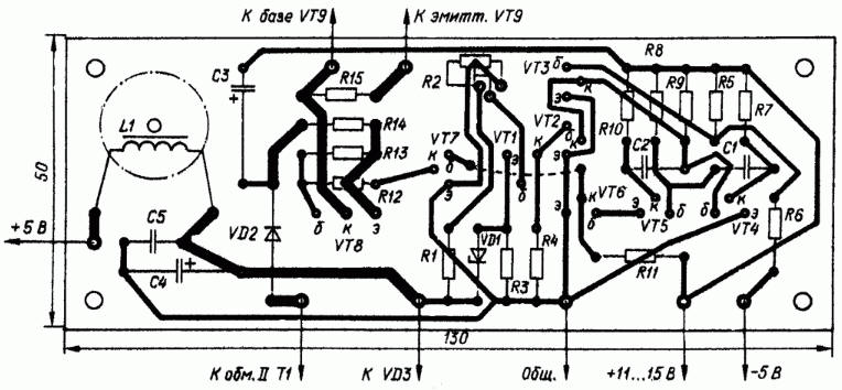
Encyclopedia of radio electronics and electrical engineering / Power Supplies The proposed voltage stabilizer for the power supply of memory devices is designed taking into account the requirements for a computer power supply, and is practically free from some of the disadvantages inherent in similar devices. The connection of the output of the unit with the input is transformer, which excludes the possibility of increasing the output voltage in case of failure of the key transistor. The high efficiency of the stabilizer (more than 75%) simplifies the problem of heat removal. The device does not contain scarce parts and is not critical to their parameters. Due to the fact that some memory chips are prohibited from supplying +5 V without a voltage of -5 V, the described stabilizer provides the possibility of blocking it when the -5 V input voltage fails. The stabilizer allows you to set the output voltage within 2 ... 40 V. The device (Fig. 1) is formed by a multivibrator on transistors VT4 and VT5 with a pulse duty cycle regulator on a transistor VT2; current amplifier on transistors VT6 and VT7; voltage boost unit, consisting of winding P of transformer T1, diode VD2, resistor R14 and capacitor C3; output node, which includes the winding III of the transformer T1, the rectifier on the diode VD3, the output filter L1C4-C6; comparison node on transistor VT1, zener diode VD1 and resistors R1-R4. The main technical characteristics of the stabilizer:
The stabilizer can also operate at a load current less than the specified one, however, the ripple level may exceed 0,25 V. This is due to a decrease in the conversion frequency of the stabilizer. You can reduce the ripple by replacing the filter capacitors C4-C6 with others with a larger capacity. An increase in the supply voltage of the stabilizer also leads to an increase in the level of ripples. When power is applied to the unit and there is a voltage of 5 V, the transistors VT1, VT2 and VT3 are closed, so the multivibrator starts to work at a certain frequency. Fixed duration multivibrator pulses, current amplified by transistors VT6 and VT7, open the key transistors VT8, VT9, and current begins to flow through them into the I winding of the pulse transformer T1. After closing the key transistors, the self-induction voltage of the transformer, taken from the windings II and III, through the diodes VD2 and VD3 charges the capacitors C3 and C4, respectively. In the event of an increase in the voltage on the capacitor C6 more than 5 V, transistors VT1 and VT2 open, which leads to an increase in the duty cycle of the multivibrator pulses and, consequently, a decrease in the output voltage of the unit. Winding II of the pulse transformer, together with the diode VD2 and capacitor C3, form a source of voltage boost - a constant voltage of 2 ... 3 V, which does not allow the VT8 transistor to saturate and thereby increases the speed of the key stage and the efficiency of the device as a whole. The blocking unit, which turns off the power of the memory device in the event of a -5 V voltage failure, is formed by the transistor VT3 and resistors R5, R6. When this voltage disappears, the VT3 transistor immediately opens completely and shunts the base circuit of the VT4 transistor with low resistance, blocking the operation of the stabilizer multivibrator. Fixed resistors of the block - MLT, tuning R1 - SP5-16; capacitors - KM-5, KM-6. K50-6. The VT9 transistor and the VD3 diode are mounted on one common copper heat-removing plastic with dimensions of 135x50x2 mm through mica spacers. The T1 pulse transformer is wound on a B36 armored magnetic circuit made of 2000NM ferrite with a paper gasket 0,2 mm thick between the cups. Windings I and III are made with a bundle of 10 PEV-2 0,2 wires and contain 10 and 6 turns, respectively. Winding II - 3 turns of wire PEV-2 0,2. Choke L1 is wound on a ring of size K20x10x6 made of ferrite 2000MM. The winding contains 20 turns of PEV-2 0,5 wire. Author: S. Shvetsov
Machine for thinning flowers in gardens
02.05.2024 Advanced Infrared Microscope
02.05.2024 Air trap for insects
01.05.2024
▪ UAVOS drone with record run time ▪ Atomic clock on quantum entanglement ▪ Hydrogen sailboat Nemesis Yacht
▪ section of the site Normative documentation on labor protection. Article selection ▪ article Vanity of vanities and all kinds of vanity. Popular expression ▪ article How absurdly did American lawyer Clement Vallandigham die? Detailed answer ▪ article Electrician of gas stations. Standard instruction on labor protection ▪ article Flasher - direction indicator. Encyclopedia of radio electronics and electrical engineering
Home page | Library | Articles | Website map | Site Reviews
www.diagram.com.ua |


 Leave your comment on this article: