|
|


 Arabic
 Bengali
 Chinese
 English
 French
 German
 Hebrew
 Hindi
Hindi Italian
 Japanese
 Korean
 Malay
Malay Polish
 Portuguese
 Spanish
 Turkish
 Ukrainian
 Vietnamese
|
ENCYCLOPEDIA OF RADIO ELECTRONICS AND ELECTRICAL ENGINEERING Microdrill power supply. Encyclopedia of radio electronics and electrical engineering
Encyclopedia of radio electronics and electrical engineering / Power Supplies To improve the convenience of using a microdrill when drilling holes in printed circuit boards, radio amateurs use various devices for its power supply [1-3]. The algorithm of their work is simple. In the absence of a mechanical load, a reduced voltage is supplied to the electric motor of the microdrill, at which the frequency of rotation of its shaft is low. With an increase in load (during drilling), the current consumed by the electric motor increases and the supply voltage automatically increases to the nominal value, which ensures normal drilling. At the end of drilling, the voltage and shaft speed are reduced again.
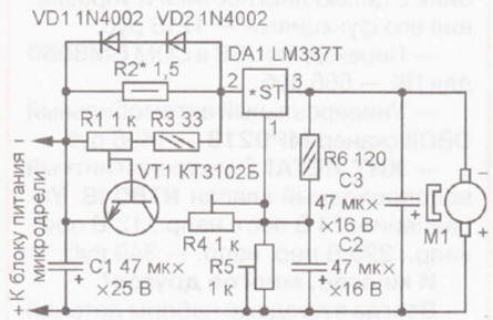
The algorithm of operation of the proposed device is the same, the scheme of which is shown in Fig. 1. It is designed to work with the standard power supply of the microdrill. Its basis is an adjustable integrated voltage regulator LM337T (DA1). As you know, the output voltage of this stabilizer depends on the voltage at its control input (pin 1), which in this case is set by the resistive divider R5R6. Without load, the current through the motor M1 is less than the threshold value, so the voltage at the current sensor - resistor R2 is not enough to open the transistor VT1. In this mode, the voltage on the electric motor is set with a tuning resistor R5 so that its shaft rotates relatively slowly. With the start of drilling, the load on the motor shaft and the current consumed by it increase. The increased voltage drop across the resistor R2 opens the transistor VT1 and through the resistor R4, voltage is supplied to the control input of the stabilizer DA1 from the negative power line. This leads to an increase in voltage on the motor, so the frequency of rotation of its shaft increases. At the end of drilling, the current consumed by the motor decreases, the transistor VT1 closes and the output voltage of the stabilizer decreases again. The threshold for opening the transistor is set by a trimming resistor R1, and the maximum voltage on the motor is set by resistor R4. Capacitor C2 provides a smooth increase and decrease in the supply voltage of the electric motor, C3 suppresses interference during its operation. Diodes VD1, VD2 limit the voltage drop across the current sensor R2. They can be omitted if, at the maximum current consumed by the electric motor, it does not exceed 1,2 ... 1,4 V. Parts of the device - almost any small-sized, no special requirements are imposed on them. The voltage stabilizer DA1 must be equipped with a heat sink with a cooling surface area of at least 20 cm2. Resistor R2 is selected so that in idle mode the voltage drop across it does not exceed 0,2..,0,3 V, and when drilling increases to 0,9 ... 1 V.
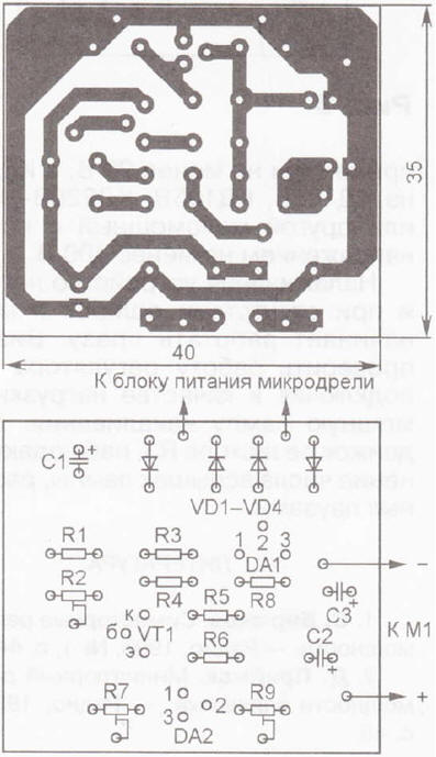
A diagram of a device that can be used with any power supply that provides sufficient voltage and current for the operation of the electric motor is shown in fig. 2. Unlike the first one, it contains a rectifier bridge VD1-VD4 and a parallel voltage regulator DA2. Therefore, even if the power supply is not stabilized, the voltage on the electric motor will change within strictly established limits. In addition, if the supply voltage is alternating, it is rectified by the diode bridge VD1-VD4 (the ripple is smoothed out by the capacitor C1), and if it is constant, then it is supplied to the device elements in the required polarity, regardless of the polarity of the input voltage. The idle speed of the motor shaft is set by the trimmer resistor R9, the threshold current value at which the transistor VT1 opens, by selecting the resistor R1 (roughly) and the trimmer resistor R2 (smoothly), the maximum voltage on the electric motor is resistor R7. The ratings of the elements in the diagram are indicated for powering the DPM-ZON1-9 electric motor. The modes of its operation are as follows: no-load current - 120 mA at a voltage of 3 V, current in the drilling mode - 600 ... 700 mA at a voltage of 8 V.
The details of the device are mounted on a printed circuit board (Fig. 3) made of foil fiberglass. Fixed resistors - MLT, S2-23, R1-4, tuning resistors - SPZ-19a, capacitors - imported oxide. The voltage stabilizer DA1 is equipped with a U-shaped heat sink, bent from a strip of sheet (3 mm thick) aluminum alloy with dimensions of approximately 50x19 mm. We can replace the KT3102B transistor with any of this series, the TL431CLP voltage regulator with any foreign analogue in the TO-92 package or the domestic KR142EN19, 1N4002 diodes with any 1N400x series. Instead of the LM337T chip, the LM317T can be used in both devices, but in this case it is necessary to change the polarity of the inclusion of oxide capacitors, diodes and an electric motor, use a pnp transistor (for example, the KT3107 series), and in the second device also swap resistors R6, R7 and conclusions 2 and 3 chips DA2. In addition, it should be noted that the pinout of the LM337T and LM317T microcircuits (in the T0-220 package) is different: the latter has an input - pin 3, and an output - pin 2. The appearance of the mounted board is shown in fig. 4. It is placed in a plastic case of suitable dimensions. The power switch can be inserted into the break of any power line. Literature
Author: I. Nechaev
Machine for thinning flowers in gardens
02.05.2024 Advanced Infrared Microscope
02.05.2024 Air trap for insects
01.05.2024
▪ Smartphone charger converts household noise into electricity ▪ Marvell PA800 anti-tamper chip
▪ section of the site Metal detectors. Article selection ▪ financial management article. Crib ▪ article How is ice cream made? Detailed answer ▪ mushroom article. Travel Tips ▪ article Both charge and weld. Encyclopedia of radio electronics and electrical engineering ▪ article Four robbers. Focus Secret
Home page | Library | Articles | Website map | Site Reviews
www.diagram.com.ua |


 Leave your comment on this article: