|
|


 Arabic
 Bengali
 Chinese
 English
 French
 German
 Hebrew
 Hindi
Hindi Italian
 Japanese
 Korean
 Malay
Malay Polish
 Portuguese
 Spanish
 Turkish
 Ukrainian
 Vietnamese
|
ENCYCLOPEDIA OF RADIO ELECTRONICS AND ELECTRICAL ENGINEERING Stabilized power supply for soldering irons. Encyclopedia of radio electronics and electrical engineering
Encyclopedia of radio electronics and electrical engineering / Power Supplies In the workshop of a radio amateur, soldering irons of various capacities are needed. A 10 ... 15 W soldering iron is used for soldering the smallest parts, for 25 W - when mounting printed circuit boards. There can be several soldering irons with a power of 40 W, with a different tip shape. They are used for both assembly and dismantling of parts. A 100W soldering iron is used for massive parts.
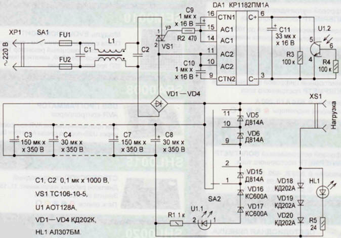
Soldering irons are usually purchased at different times, from different manufacturers, and they behave differently at a nominal mains voltage of 220 V: some overheat, others work with underheating. It is impossible to perform high-quality soldering in both cases. Voltage fluctuations in our electrical networks sometimes do not fit into the interval prescribed by the standard. The power of a 40-watt soldering iron, for example, varies from 29 to 48 watts. Naturally, the temperature of the soldering rod also changes. Working with a soldering iron requires various tricks. I have developed a stabilized power supply that maintains the optimal voltage for a soldering iron or similar load with a power of 10 to 250 W when the mains voltage changes from 160 to 250 V. It allows you to quickly set the desired heating temperature both during operation and when changing the soldering iron (load ). On fig. 1 shows a diagram of the proposed unit. It contains a bridge network rectifier on diodes VD1-VD4, smoothing capacitors C3-C8, a phase regulator controlled by an optocoupler U1 on a DA1 chip [1, 2] and a triac VS1, zener diodes VD5-VD17 to control the optocoupler. The input power filter C1L1C2 reduces the level of interference that occurs during the operation of the device and penetrates into the network. A soldering iron is included in the XS1 socket. Let's consider the operation of the unit when the mains voltage is supplied by the switch SA1. Capacitor C11 begins to charge, and the voltage at its terminals increases, respectively, the open angle of the phase regulator DA1 G11 and the triac VS1 increases. The voltage rectified by the diode bridge VD1-VD4 across the filter capacitors C3-C8 also begins to increase. When the stabilization voltage is reached, current begins to flow through the zener diodes VD5-VD17 and the emitting diode U1.1 of the optocoupler. The phototransistor U1.2 opens, discharging the capacitor C11. Its discharge leads to a decrease in the angle of the open state of the phase regulator. Capacitors 03-08 start to discharge through the soldering iron. The voltage on them decreases, as does the current through the zener diodes VD5-VD17 and the radiating diode U1.1 of the optocoupler, the open angle of the phase regulator DA1 again increases, then the process repeats. The average value of the output voltage will depend on the position of the SA2 switch. The position of the switch determines the number of zener diodes connected. By changing the number of zener diodes, you can adjust the voltage supplied to the soldering iron, and thereby set its temperature. It will be independent of the mains voltage. The adjustment step is determined by the stabilization voltage of the VD5-VD15 zener diodes and for D814A it is 7,5 V. Using other zener diodes, the adjustment step can be changed. On the diodes VD18-VD20, the LED HL1 and the resistor R5, the indication unit is assembled. The current flowing through the soldering iron creates a voltage drop across these diodes that is sufficient for the HL1 LED to glow, which indicates the presence of output voltage and the health of the soldering iron.
The block is assembled by hinged installation. A C1L1C2 surge protector, a DA1 chip with the elements necessary for its operation, VD16, VD17 zener diodes, a resistor R2 and an optocoupler U1 are installed on a segment of the universal breadboard. Zener diodes VD5-VD15 are mounted on the terminals of the switch SA2. The device is placed in a tin case (Fig. 2) with dimensions of 140x220x60 mm from confectionery. On the front panel there is a switch SA1, a switch SA2, an LED HL1 and a socket XS1. The case is painted with heat-resistant enamel and is used as a stand for a soldering iron, therefore, on its cover there is a support for a soldering iron and cups for rosin, solder, made from parts of a telephone set with an electromechanical bell. The dimensions of the case are such that you can not limit yourself in choosing the size of the parts. Capacitors C3-C8 - K50-12 from old television equipment, any with a total capacity of 500-800 microfarads for a voltage of at least 350 V will do. Diodes VD1-VD4 must withstand a reverse voltage of at least 400 V and forward current of at least 2 A, VD18- VD20 - direct current of at least 1,5 A. The HL1 LED must be selected with a forward voltage of 1,8-..2 V, with more, another KD18A diode is added to the VD20-VD202 circuit. Switch SA2 - 11P1N-PM, switch SA1 - any with a switching current of at least 2 A. Fusible inserts FU1, FU2 for a current of 5 A, 250 V. Low-power zener diodes can be both domestic and imported, both in metal and in glass cases. Instead of KS600A zener diodes, you can use a circuit from others with a total stabilization voltage of 180 ... 200 V, for example, four KS551A zener diodes. Instead of Zener diodes D814A - with a stabilization voltage of 6 to 9 V, for example, KS162A-KS191A. Optocoupler U1 - AOT128 with any letter index or imported 4N25-4N35. Triac VS1 - for a voltage of at least 500 V and a current of 10 A. The inductor L1 is used ready from the UPIMCT TV. Capacitors C1, C2 network filter - K78-2. It is undesirable to use capacitors K73-17 because of their insufficiently reliable operation in network circuits. Resistors and other capacitors can be any. The unit does not require adjustment, if necessary, you should select the optimal voltage for each existing soldering iron. By changing the voltage switch SA2, determine the position at which the temperature of the soldering rod is optimal. After each switching, it is necessary to give an exposure of 5 ... 10 minutes so that the rod finally warms up. For each soldering iron, a tag is made on which the optimal switch position is written. It is very convenient to attach it to the handle of the soldering iron with transparent adhesive tape. This will allow you to quickly set the optimal position of the SA2 switch for each soldering iron during operation, quickly changing them if necessary. Literature
Author: K. Moroz
Artificial leather for touch emulation
15.04.2024 Petgugu Global cat litter
15.04.2024 The attractiveness of caring men
14.04.2024
▪ Politicians to discuss killer robots ▪ Graphene film will reliably protect against corrosion ▪ Schizophrenia-causing cells identified ▪ People's memory works better in the dark.
▪ site section Lightning protection. Article selection ▪ article Construction of a semi-copy model. Tips for a modeller ▪ article Who discovered the atom? Detailed answer ▪ article The functional composition of Toshiba TVs. Directory ▪ article Mirror halogen lamps. Encyclopedia of radio electronics and electrical engineering
Home page | Library | Articles | Website map | Site Reviews
www.diagram.com.ua |


 Leave your comment on this article: