|
|


 Arabic
 Bengali
 Chinese
 English
 French
 German
 Hebrew
 Hindi
Hindi Italian
 Japanese
 Korean
 Malay
Malay Polish
 Portuguese
 Spanish
 Turkish
 Ukrainian
 Vietnamese
|
ENCYCLOPEDIA OF RADIO ELECTRONICS AND ELECTRICAL ENGINEERING Powerful stabilized DC voltage converter for powering network equipment. Encyclopedia of radio electronics and electrical engineering
Encyclopedia of radio electronics and electrical engineering / Voltage converters, rectifiers, inverters The proposed device is designed to power equipment operating from a 220 V 50 Hz network in the field, as well as during an emergency shutdown of the AC network. The converter has a block design. It supplies the load with a stabilized DC voltage of 310 V or an alternating pulse voltage of the same amplitude with an effective value of 220 V. Adding an LC filter makes it possible to obtain a sinusoidal AC voltage of 220 V. Electrical appliances are widely used in everyday life of modern man. In the overwhelming majority of cases, the source of energy for them is a 220 V alternating current network. At the same time, power supply in many regions of our country is not highly reliable. In amateur radio literature, many articles have been published on battery DC-to-AC converters suitable for supplying consumers during a power outage. They can work on the principle of low-frequency [1-4] or high-frequency [5, 6] conversion. Each of these types of converters has its own characteristics. Low-frequency ones have a large mass and dimensions due to the use of a low-frequency transformer. In the converter [3], only the average rectified value of the output voltage is stabilized, but the amplitude and effective values are not stabilized, which in some cases can lead to damage to the supplied loads. The converter [4] uses stepwise adjustment of the output voltage without feedback, which does not provide high stability of the output voltage. Transducers operating at ultrasonic frequencies (tens of kilohertz) [5, 6] are better in terms of weight and size, but their output power does not exceed 300 W. The author needed to power loads of greater power. When developing the proposed device, the author tried to preserve the advantages of high-frequency conversion and increase the output power to 1 kW. Main Specifications (at ambient temperature 13...20 °С)
The converter consists of four blocks: a high-frequency generator, the circuit of which is shown in fig. 1, a high-frequency inverter with a rectifier - voltage multiplier (Fig. 2), a low-frequency generator (Fig. 3) and a low-frequency bridge inverter-switch (Fig. 4).
The high-frequency generator block (see Fig. 1) contains an input voltage control unit on the VT1 transistor and K1 relay, a 9 V internal supply voltage regulator on the DA1 chip, a 27 kHz pulse generator on the DD1.1 and DD 1.2 logic elements, delay nodes fronts of pulses on elements VD4, R4, C2 and VD5, R5, C3, shapers of control pulses on elements DD1.3, DD1.4, DD2.3, DD2.4 with output emitter followers on transistors VT2-VT5, unit for controlling the amplitude of the output voltage on the elements DD2.1, DD2.2.
The high-frequency inverter unit (see Fig. 2) contains a push-pull cascade on powerful field-effect transistors VT6-VT9 and a transformer T1, as well as a rectifier with a fourfold voltage multiplication on diodes VD6-VD9 and capacitors C7-C10. This unit generates a constant stabilized voltage of 300.310 V. If it is known that the AC supply voltage is rectified and smoothed in the load, then such a load can be connected to this unit through a fuse with a rated current of 5 A (see the editorial note to article [5]). In this case, the remaining blocks are not needed.
The low-frequency generator unit (see Fig. 3) contains a 9 V internal supply voltage stabilizer on the DA2 chip, a 50 Hz pulse generator on the DD3.1 and DD3.2 logic elements, current-limiting resistors R18 and R19, pulse edge delay nodes on the elements VD12, R20, C14 and VD13, R21, C15, control pulse shapers on elements DD3.3, DD3.4, DD4.3, DD4.4 output emitter followers on transistors VT11-VT14, load current limiter on transistor VT10 and elements DD4.1 .4.2, DDXNUMX.
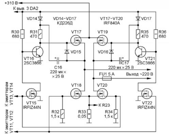
The bridge low-frequency inverter-switch (Fig. 4) contains a bridge on powerful key field-effect transistors VT17-VT20 and a current sensor - resistor R33. Control pulses are applied directly to the gates of the lower transistors VT18 and VT20 according to the scheme, and to the gates of the upper ones according to the VT17 and VT19 scheme - through the upper-side inverters. One inverter is assembled on the elements VT15, VT16, R30, R31, C16, VD14, VD15, the second - on VT21, VT22, R35, R36, C17, VD16, VD17. A constant voltage of 310 V is supplied to one diagonal of the bridge, and a load is connected to the other through the fuse FU1. The converter works like this. If the voltage of the supply battery is more than 10,5 V, the transistor VT1 opens, the relay K1 is activated and through its contacts K1.1 the supply voltage is supplied to the voltage stabilizers on the DA1 and DA2 microcircuits. When the battery voltage drops below 10,5 V, transistor VT1 closes, contacts K1.1 open and turn off the power to the generators, as a result of which all switching transistors VT6-VT9 are closed, the converter turns off. The turn-on voltage is regulated by a tuning resistor R3. Due to the fact that the turn-on voltage of the electromagnetic relay K1 is greater than the turn-off voltage, the characteristic of the node on the transistor VT1 has a small hysteresis, sufficient for practical use. The oscillation frequency of the generator on the elements DD1.1 and DD1.2 depends on the resistance of the resistors R1, R2 and the capacitance of the capacitor C1. From the anti-phase outputs of the generator (pins 3 and 4 of the DD1 microcircuit), the pulses are fed to the nodes of the delay of the pulse fronts. At the same time, their recessions are transmitted with virtually no delay. The edge delay time is determined by the time constants of the R4C2 and R5C3 circuits, which must be the same. The characteristics of the shapers have hysteresis, the value of which depends on the ratio of the resistances of the resistors of the positive feedback circuits (PIC) R6 and R8, R7 and R9. From the outputs of the shapers, the control pulses through emitter followers on transistors VT2-VT5 are fed to the gates of the key transistors VT6-VT9. The rectifier on diodes VD6-VD9 and capacitors C7-C10 is made with a fourfold voltage multiplication for the following reason. It is desirable to wind the primary and secondary windings of the transformer in one layer in order to reduce the leakage inductance. The use of a voltage multiplier allows four times to reduce the number of turns in the secondary winding and make it single-layer. The voltage from the output of the rectifier is supplied to the divider R10R11. A voltage proportional to it from the engine of the tuning resistor R11 is fed to the input of the node on the elements DD2.1 and DD2.2 with a PIC circuit on resistors R12 and R13, which creates a switching characteristic with hysteresis. After the power is turned on, the output voltage of the rectifier increases. When it reaches the upper switching threshold (310 V), a low level is set at the output of the DD2.1 element, connected to pins 9 of the DD1 and DD2 microcircuits, which prohibits the passage of pulses to the emitter followers, as a result of which all key transistors are closed. After that, the output voltage of the rectifier decreases due to the discharge of the capacitors C9 and C10. When it drops to the lower switching threshold (300 V), a high level is set at the output of the DD2.1 element, which again allows the passage of pulses to the emitter followers, as a result of which the output voltage of the rectifier will increase to the upper threshold. By moving the slider of the tuning resistor R11, you can adjust the output voltage of the rectifier, and by selecting the resistor R13 - the difference in switching thresholds. Increasing the resistance of the resistor R13 reduces it, and reducing it increases it. The nodes of the low-frequency generator (see Fig. 3) are similar to the corresponding nodes of the high-frequency one, but the capacitance of the time-setting capacitors of the low-frequency generator is greater, so resistors R18 and R19 are added to it, which limit the discharge current of capacitors C14 and C15, protecting the outputs of the DD3 chip (pins 3 and 4 ) from overload. On the transistor VT10, elements DD4.1, DD4.2 and resistors R25, R26, R29, the unit for protecting the converter from overloads is assembled. When the load current of the converter exceeds the allowable value, the voltage across the resistor R33 - the current sensor - increases to 0,7 V. In this case, the transistor VT10 opens, a low level is set at the output of the DD4.2 element, which goes to the pins 9 of the DD3 and DD4 microcircuits, in as a result, the passage of pulses to emitter followers on transistors VT11-VT14 is prohibited. All key transistors of the bridge VT17-VT20 are closed. Bridge low-frequency inverter-switch (Fig. 4) operates as follows. During the pause between pulses, the voltage at the outputs of the above emitter followers is zero, so transistors VT16 and VT21 are open, and all others are closed. When a pulse arrives at the gates VT15 and VT20, these transistors, as well as VT17, open. When a pulse arrives at the gates VT18 and VT22, these transistors, as well as VT19, open. As a result, rectangular bipolar voltage pulses separated by pauses with a range of 620 V and an effective value of 220 V are formed at the bridge output. Since the control pulses are separated by pauses, the appearance of a through current through the series-connected bridge transistors is excluded.
Some consumers require a sinusoidal AC supply voltage. In this case, the low-frequency generator assembly (see Fig. 3) is replaced by another, the circuit of which is shown in Fig. 5. This unit uses a 50 Hz sinusoidal voltage generator at the op amp DA4.1, a phase inverter at the op amp DA4.2, two integrating circuits R44C25 and R49C30, two emitter followers VT23 VT24, VT25 VT26 and two adders on resistors R50R52R54 and R51R55R57.
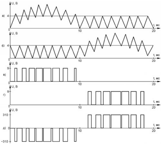
The positive half-wave of the sinusoidal voltage from the output of the OUDA4.1 through the diode VD21 is fed to the adder R51R55R57. The positive half-wave from the output of the phase inverter DA4.2 is fed through the diode VD20 to the adder R50R52R54. From the outputs of the adders, the voltage through the resistors R53 and R56 is fed to the input of the pulse shapers DD5.1, DD5.2, DD6.1, DD6.2. Rectangular pulses are fed to the inputs of the integrating circuits, and sawtooth pulses are formed on capacitors C25 and C30, which are fed through capacitors C26 and C31 to the inputs of two pulse shapers. Stress diagrams in fig. 6 show how the pulses at the inputs of the shapers are summed over one period of a frequency of 50 Hz. To visualize the shape of the pulses, the high-frequency duty cycle (27 kHz) is extended. On fig. 6, a - voltage at pin 8 of the DD5 microcircuit; in fig. 6b - at pin 8 of the DD6 chip. As a result, sequences of pulses with a sinusoidal PWM frequency of 50 Hz are formed at the outputs of the shapers: in fig. 6, c - at the output of DD5,2; in fig. 6,d - at the output of DD6.2. At the output of the "~220 V" converter, a bipolar PWM signal with a swing of 620 V is formed, the shape of which is shown in fig. 6, d. In order to suppress the component with a frequency of 27 kHz in the output voltage, a choke must be connected in series with the load, and a capacitor must be connected in parallel with the load. These elements are selected experimentally for each load. For example, a load with a power of 100 W (its resistance is 484 ohms) requires a filter with a choke with an inductance of 0,13 H and a capacitor with a capacitance of 0,56 microfarads. With a different load resistance, the inductance of the inductor is recalculated in direct proportion, and the capacitance of the capacitor is inversely proportional to the load resistance. All parts of the transducer are housed in a sheet aluminum housing. Transistors VT6-VT9, VT17-VT20 are fixed on the case using heat-conducting paste and mica gaskets. Transistors IRFIZ44N (VT15 and VT22) are installed without gaskets, as their cases are completely insulated. They can be replaced with IRFZ44N, but then they must be installed through mica spacers.
The computer power supply fan with a 1W M3 electric motor constantly blows air through the case to cool parts. To reduce energy consumption at low-power loads, the fan can be turned off by switch SA1. Transformer T1 is wound on four magnetic cores stacked together from a horizontal transformer TVS-110, as shown in fig. 7. The numbers indicate: 1 - winding wire; 2 - magnetic circuit; 3 - a clamp that tightens the magnetic circuit. Primary windings (I and II) contain four sections of three turns of 5 mm2 wire (two 2,5 mm2 installation wires put together). The secondary winding (III) contains two sections of 11 turns of mounting wire with a cross section of 1,5 mm2. The turns of the windings must be evenly distributed along the length of the magnetic circuit, and the windings must be single-layer. The remaining elements are mounted on two separate boards by surface mounting. The board with the elements shown in fig. 1 is located in close proximity to the key transistors (see Fig. 2). The board with the elements shown in fig. 3, - next to the transistors of the bridge low-frequency inverter-switch (see Fig. 4). Capacitor C6 is desirable to use an imported oxide from the "Low ESR" category, for example, Jamicon WL or similar. Otherwise, it will heat up. Rectifier capacitors C7-C10 must have a sufficiently large allowable reactive power. The device uses MBGCH capacitors. In parallel to each of them, a non-inductive ceramic capacitor KM-3 of the H30 group with a capacity of 0,022 μF and a rated voltage of 250 V is connected. Trimmer resistors - from the SP3-1b series. Before installing them, it is necessary to check the serviceability of the mobile contact system. Relay K1 must have a response voltage of not more than 10 V. The author used the RES59 relay (version HP4.500.020). When setting up, instead of a battery, a laboratory power supply with an adjustable output voltage of 10.13 V is used. A voltage of 10,5 V is applied to the input of the converter, the resistor R3 is used to turn off relay K1. Then the input voltage is increased to 12 V. By selecting resistors R1 and R2 (see Fig. 1), the same pulse duration is set to 18,5 μs at pins 3 and 4 of the DD1 microcircuit. By selecting resistors R4 and R5, the duration of the pause between these pulses is 5 μs. The engine of the tuning resistor R11 - voltage +305 V at a load power of 60 W at the output of the rectifier VD6-VD9C7-C10 (see Fig. 2). The selection of resistors R16 and R17 (Fig. 3) sets the same pulse duration of 10 ms at pins 3 and 4 of the DD3 microcircuit. The selection of resistors R20 and R21 - the duration of the pause between these pulses is 6 ms. The block, the scheme of which is shown in fig. 5, adjust so. Move the trimmer resistor R39 down the circuit so that the generator on the op-amp DA4.1 stops working. By selecting capacitors C25 and C30, the sawtooth voltage swing across them is set to 4 V. Fixed resistors R52 and R55 are temporarily replaced with trimmers of 15 kOhm, included as rheostats. First, their resistance is smoothly reduced from the maximum until pulses appear at the output of the emitter followers, then they are increased until they disappear. Measure the resistance of the entered part of the tuning resistors with a digital ohmmeter and replace them with constants of the same resistance. After that, the engine of the tuning resistor R39 is moved up the circuit, setting a voltage amplitude of 4 V at the generator output. In this case, the output voltage should be in the form of a slightly truncated sinusoid. If necessary, by selecting capacitors C18 and C22, you need to set the generation frequency to 50 Hz. Then, selecting resistors R50 and R51, the amplitude of the half-wave is 4 V across resistors R54 and R57. To improve the operation of the generator on the op-amp DA4.1, it may be necessary to turn on a 47 pF capacitor between the right output of the resistor R40 according to the circuit and the common wire. Converter power sources can be car starter batteries, car on-board network, traction batteries for electric vehicles, solar panels, wind or water power generators. If necessary, the supply voltage can be doubled. To do this, the primary windings (I and II) of the transformer T1 must contain four sections of six turns of a mounting wire with a cross section of 2,5 mm2. The author uses a self-made gas generator made from a Ural chainsaw and an electric generator with an output voltage of 12 V and a power of 1 kW from a T-150 tractor, which are interconnected by a V-belt drive. In terms of power to weight, this gas generator surpasses many industrial designs. Light weight and dimensions allow you to take it on the road and, if necessary, charge the car battery in the field. A voltage converter feeds any equipment with a power of up to 1 kW. Literature
Author: A. Sergeev
Machine for thinning flowers in gardens
02.05.2024 Advanced Infrared Microscope
02.05.2024 Air trap for insects
01.05.2024
▪ Where and when were horses first tamed ▪ MATSUSHITA Starts DVD-RAM Promotion ▪ Compact device for visualization of brain activity ▪ New family of electromechanical relays FTR-MY
▪ section of the site Radioelectronics and electrical engineering. Article selection ▪ article by Antigonus. Popular expression ▪ article How far is the nearest star from us? Detailed answer ▪ article Facing tiler. Job description ▪ article Broadband power amplifier. Encyclopedia of radio electronics and electrical engineering
Home page | Library | Articles | Website map | Site Reviews
www.diagram.com.ua |


 Leave your comment on this article: