|
|


 Arabic
 Bengali
 Chinese
 English
 French
 German
 Hebrew
 Hindi
Hindi Italian
 Japanese
 Korean
 Malay
Malay Polish
 Portuguese
 Spanish
 Turkish
 Ukrainian
 Vietnamese
|
ENCYCLOPEDIA OF RADIO ELECTRONICS AND ELECTRICAL ENGINEERING Refinement of the power supply AV3302. Encyclopedia of radio electronics and electrical engineering
Encyclopedia of radio electronics and electrical engineering / Power Supplies The small-sized AV3302 network adapter was used to power "slow" telephone modems from ZyXEL (for example, U-1496E). The device is made in the form of an "active" network plug with dimensions of 80x65x45 mm (without the pins of the plug itself) and, as follows from the label on the case, it provides an AC voltage of 25 V at the output with a maximum load current of 0,6 A. Since the era of "slow" modems is gone in the past, it is advisable to adapt this and similar network adapters to power other radio equipment. After disassembling the adapter (it is enough to unscrew two screws for this), it turned out that the device consists of a step-down transformer wound on a toroidal magnetic circuit and a 0,25 A fuse-link included in its primary winding circuit. When measuring the main parameters of the transformer, it turned out to be a pleasant surprise that its no-load current is only 2,7 mA at a mains voltage of 250 V. This is very rare for mains transformers with an overall power of 1,5 ... 20 W, both industrial and home-made . The transformer contains a secondary winding with a tap from the middle and an open-circuit voltage of about 26 V (2x13 V). The resistance of the primary winding to direct current is approximately 167 ohms, each secondary half-winding is about 1,3 ohms. For the convenience of further use, the adapter has been modified. Since a step-down transformer occupies a significant part of the volume of the case, it was decided to make an unstabilized power supply unit (PSU) based on it with two values of the output DC voltage, for which the secondary half-windings were disconnected (this is not difficult to do, since they are connected by twisting the winding wire outside the transformer).
The scheme of the upgraded device is shown in fig. 1. AC mains voltage 220 V is supplied to the primary winding of the transformer T1 through the fusible link FU1. The secondary windings of the transformer are connected to the bridge rectifier VD1-VD4 through a polymer self-healing fuse FU2 and closed contacts of the output voltage switch SA1. In its upper (according to the scheme) position, the windings II.1 and II.2 are connected in series, in the lower position - in parallel. The parallel connection of the secondary windings allows the PSU to continuously supply current up to 1 A to the load at an output voltage of 12,5 V. The use of Schottky diodes in the rectifier reduces voltage losses on it, and hence the thermal power dissipated by it. Capacitor C5 smooths out the ripple of the rectified voltage. LED HL1, transistor VT1, zener diode VD5 and resistors R1-R5 form an output voltage indication unit. If the SA1 switch is in the position shown in the diagram ("32 V"), the output voltage of the power supply unit significantly exceeds the stabilization voltage of the VD5 zener diode, so it is open, current flows through the yellow glow LED and it glows. At the same time, transistor VT1 is also open. The voltage on its collector does not exceed a few tenths of a volt, so the green LED is off. When the switch is set to the lower (according to the scheme) position ("16 V"), the voltage at the PSU output becomes less than the stabilization voltage of the Zener diode VD5, so it and the transistor VT1 close. As a result, the yellow LED goes out, and a current limited by resistor R1 flows through the green LED, and it glows.
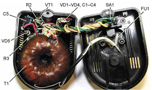
Due to the lack of free space in the body of the device, the installation was carried out in a volumetric way - new parts are glued to its walls with Quintol polymer glue so that the ventilation holes do not overlap. Resistors - any small-sized (MLT, S1-4, S1-14, S2-23, S2-33). The oxide capacitor C5 is glued into the corner of the case with the leads facing up (Fig. 2). Capacitors C1-C4 are small film capacitors. Their leads are soldered to a prefabricated diode bridge, as shown in Fig. 3, after which the capacitor cases are glued to the upper (according to Fig. 2) wall of the case. The HL1 LED is glued into a hole drilled in it. Transformer T1 is also fixed with glue.
Instead of the KS518A zener diode, you can use any of the 2S518A, KS520V, 1N4746A 1N4747A TZMC-18, TZMC-20. Possible replacement of Schottky diodes SR360 - SR306, MBRS360T3, MBRD360, MBR360. In the absence of such diodes, you can also use conventional silicon ones, designed for an average rectified current of 2.3 A and a reverse voltage of 60 V (KD257A, 1N5404 and the like) or a ready-made diode bridge, for example RS202. Instead of the 2SC1815 transistor, any of the KT3102, KT6111, KT645 series, as well as imported 2SC1815, 2SC1845, SS9013, SS9014 (taking into account the differences in the pinout) will do. The L-59GYW two-color LED can be replaced by another similar one with a common cathode without built-in resistors, for example, the L-59, L-119, L-239, L-799 series. To switch the transformer windings, a small-sized imported two-pole switch from a 230/115 V operating voltage switching unit was used, designed for switching 1 A alternating current. It does not have a protruding lever (it can only be switched with a screwdriver or other sharp object) and, in addition, is installed in on the side of the plug pins, which prevents accidental switching of the output voltage (to do this, the plug must be removed from the socket). Similar switches, designed for a larger switching current, are used in computer power supplies. Fusible insert FU1 (at 0,5 A) is installed between the pins of the mains plug (Fig. 3). The use of an insert for twice as much (than in the original device) current is dictated by the requirement that the self-restoring fuse FU2 has time to operate before the insert burns out. Possible replacement for the polymer fuse MF-R110 - LP30-110, LP60-110. The appearance of the modified adapter is shown in Fig. 4. When you turn it on for the first time, it is recommended not to connect the load, but to turn on an incandescent lamp with a power of 15 ... 25 W at 220 V in the primary winding circuit of the transformer. A bright lamp will indicate incorrect phasing of the secondary windings or installation errors. In the absence of a bright glow of the lamp, they are convinced at both positions of the switch SA1. As tests have shown, with a mains voltage of 260 V and a power delivered to the load of 17 W, there is practically no heating of the PSU case, which indicates not only the good quality of the step-down transformer, but also the presence of a power reserve. This allows you to use it to power various devices that operate around the clock or for a long time, for example, antenna amplifiers (via a voltage stabilizer), security devices, video surveillance devices, etc. In the manufacture of such a device "from scratch", a ready-made unified transformer TTP40, TP8-15-220-50, TP8-25-220-50 is suitable. You can wind the step-down transformer yourself. When using a W-shaped magnetic circuit with a cross-sectional area of \u6b\u2bthe average core of 1900 cm2, the primary winding should contain 0,18 turns of wire PEV-130 2, the secondary - 0,51 turns (strictly the same) of wire PEV-XNUMX XNUMX. The plates of the magnetic circuit should be assembled in overlap. After checking the performance of the transformer, it is recommended to impregnate the magnetic circuit with zaponlak. Author: A. Butov
Machine for thinning flowers in gardens
02.05.2024 Advanced Infrared Microscope
02.05.2024 Air trap for insects
01.05.2024
▪ MAX14851 - universal 6-channel 600V digital isolator ▪ Painkiller made from the world's most pungent substance ▪ LP3883 CMOS Voltage Regulator ▪ Fast SanDisk USB 3.1 Type-C SSDs
▪ section of the site Sites of amateur radio equipment. Article selection ▪ article Forward, towards the dawn. Popular expression ▪ article Which object in London was originally named Big Ben? Detailed answer ▪ article Jamaican pepper. Legends, cultivation, methods of application ▪ article Electric wonders. Chemical experience
Home page | Library | Articles | Website map | Site Reviews
www.diagram.com.ua |


 Leave your comment on this article: