|
|


 Arabic
 Bengali
 Chinese
 English
 French
 German
 Hebrew
 Hindi
Hindi Italian
 Japanese
 Korean
 Malay
Malay Polish
 Portuguese
 Spanish
 Turkish
 Ukrainian
 Vietnamese
|
ENCYCLOPEDIA OF RADIO ELECTRONICS AND ELECTRICAL ENGINEERING Switching voltage regulator on the MC34165P chip. Encyclopedia of radio electronics and electrical engineering
Encyclopedia of radio electronics and electrical engineering / Power Supplies With a large difference between the input and output DC voltage, it is advisable to use switching voltage stabilizers, which in this case provide a higher efficiency compared to linear stabilizers. Using specialized microcircuits for these purposes, it is possible to significantly simplify the development, assembly and adjustment of switching stabilizers. The stabilizer on a Motorola microcircuit, brought to the attention of readers, provides an adjustable output voltage from 1,2 to 15 V at a load current of up to 1 A. If there is a relatively high-voltage source of direct or alternating voltage, for example, a power supply from an old printer, scanner, desktop accounting calculator, a switching voltage regulator can be made on an integrated circuit MC34165P, which allows input DC voltage up to 65 V. Step-down, step-down, step-up and inverting DC-DC converters (so-called DC-DC converters). It is similar in its functions to the more well-known low-power microcircuits of the MC34063, MC33063 series, but allows a higher load current and a higher input voltage.
The circuit of the step-down DC voltage regulator, assembled on the MC34165P chip, is shown in fig. 1. The stabilizer is made as a universal device, it is designed for an input AC voltage of 8 ... 42 V or a constant 8 ... 60 V and provides an output voltage of 1,2.15 V at a load current of up to 1 A. This output voltage range is most often used for powering various low-power industrial and amateur radio designs. The minimum input DC or AC voltage must be approximately four volts or more above the specified output voltage. Polymer self-restoring fuses FU1, FU2 protect input voltage sources from overload in case of stabilizer malfunctions. Diode VD1 protects the stabilizer from the wrong polarity of the input voltage. The diode bridge VD2 rectifies the AC voltage. Capacitor C6 smooths out the ripple of the rectified voltage. LED HL1 blue glow indicates the presence of input voltage. The DA1 chip is connected according to the step-down voltage regulator circuit, close to the typical one. The output voltage of the stabilizer depends on the ratio of the resistance of resistors R5 and R3. The greater the set resistance of the variable resistor R5, the higher the output voltage. The maximum output voltage for this device is selected to be 15 V, but you can adjust the regulator to a different, higher or lower value. Resistor R2 is a current sensor for the operation of the protection unit of the DA1 microcircuit. The frequency of the internal oscillator of the DA1 chip depends on the capacitance of the capacitor C8, with the value indicated on the diagram, it is approximately equal to 60 kHz. Resistor R4 and diode VD3 reduce the likelihood of damage to the microcircuit. Choke L1 - storage. The stabilizer output voltage ripple is smoothed out by capacitor C9. The stabilized voltage is supplied to the output of the power supply through a two-section LC filter L2C12-C14L3C15-C17. To improve the reliability of relatively low-voltage capacitors C10-C13 and C15, C16 are connected in series. The HL2 LED turns on when the output voltage of the stabilizer exceeds 2 V. Resistor R7 discharges the capacitors C9-C17 when the output voltage of the stabilizer decreases or the power is turned off. A VD5 zener diode with a nominal stabilization voltage of 20 V can protect some connected loads from damage in the event of a stabilizer malfunction. With an input constant voltage of 45 V, an output of 15 V and no load, the current consumed by the stabilizer does not exceed 21 mA. When the input voltage is 42 V, the output is 9 V, and the load current is 1 A, the current consumed by the regulator from the source is about 0,28 A, which corresponds to an efficiency of 76%. With an input voltage of 42 V, an output of 5 V and a load current of 1 A, the stabilizer consumes a current of about 0,19 A, the efficiency is approximately 62%. For comparison, the efficiency of a conventional linear regulator in the first case is approximately 27%, and in the second only 13%. In this case, the control element - a transistor - would need to be installed on an impressive heat sink with a large cooling surface area. The amplitude of the voltage ripple and noise at the output of the stabilizer is less than 5 mV at a load current of 1 A.
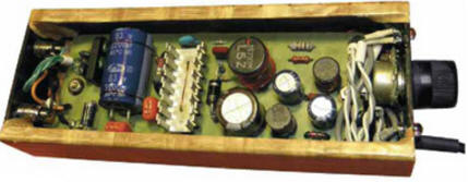
Most of the parts of the voltage regulator are located on a 130x45mm circuit board. The whole structure is placed in a metal case measuring 155x57 mm with plastic inserts fig. 2. The metal parts of the case are pasted over with a decorative self-adhesive film "under the tree". The housing is electrically connected to a common wire. The point of connection of the case to the common wire is the negative terminal of the capacitor C9, the shielding braid of the wire going to the variable resistor R5 is connected to the same point. The length of this wire should be as short as possible. Resistors in the device can be used for any general application, for example, MLT, C1-4, C1-14, C2-23. Variable resistor - SP4-1, SP4-3, SP3-9, SP3-33-32, its metal case-screen is connected to a common wire. Oxide capacitors - low-profile imported analogues of domestic K50-68, K50-35. Capacitors C1-C5, C7 are small-sized film capacitors for a rated voltage of at least 100 V. Capacitor C8 is a film or ceramic capacitor with low TKE. Capacitors C10-C13, C15, C16 ceramic for surface mounting. They are soldered under the leads of the corresponding oxide capacitors. Suitable capacitors with a capacity of 2,2 uF, according to the principle "the larger the capacitance, the better" and the larger the size of these capacitors, the better. Capacitor C18 is a small-sized surface-mount tantalum capacitor, it is installed inside the output connector (the connector is not shown in the diagram of Fig. 1). Diode bridge D2SB60 can be replaced by KBP02-KBP10, RS203-RS207, RC203-RC207. Instead of a 1N4003 diode, any of 1N4002-1N4007, UF4002-UF4007, KD243B, KD247A, KD257A will do. Diode 1N5402 can be replaced with 1N5402-1N5408 or from the KD226, KD257, KD411, KD213 series. It is permissible to replace the MR852 high-speed diode with MR851-MR856, SRP300B-SRP300K, UF5402-UF5408, other diodes from this design, including the VD2 bridge, can be replaced with the same devices. Instead of the zener diode 1 N5357, two more powerful 1.5KE10CA or one D816A connected in series will do. Any LEDs are applicable, preferably with increased light output, for example, from the KIPD21, KIPD40, KIPD66, L-1513S series. Resettable fuses FU1, FU2 - any operating voltage of 60 or 250 V, for example LP60-110. In a debugged device, conventional fuse-links can be installed instead. The MC34165P is interchangeable with the MC33165P, which allows operation over a wider temperature range. A duralumin or copper heat sink is glued to the microcircuit with BF glue, the cooling surface area of \u60b\u40bwhich should be sufficient so that the temperature of the microcircuit case does not rise above 28 ° C in all modes of operation of the voltage stabilizer. If you limit yourself to a maximum input voltage of 33163 V DC or 34163 V AC, you can use the MC3P or MC2575P chip, which allows a load current of up to 2576 A. In the absence of the mentioned chips, you can use the LM3HV-ADJ or LM4HV-ADJ. In the case of using these microcircuits, the device circuit is slightly changed (a different part is shown in Fig. 1), the resistance of the resistor R2 is increased to 3 kOhm, the resistor R15.60 is not installed, and a self-restoring fuse with an operating voltage of 900 V and a current of 60 mA is connected in series with the inductor L090, e.g. LPXNUMX-XNUMX.
It should be noted that with such a replacement, there is no need to re-calculate or select resistors R3, R5. For stable and reliable operation of the stabilizer microcircuit, the correct wiring of the high-current and signal circuits of the common wire is extremely important. To the negative terminal of the capacitor C6, separate printed conductors or wires are connected to the corresponding terminals of the elements C8, C9, VD4, terminals 3-5, 12, 13 of the DA1 microcircuit. To minimize ripple and noise at the output of the stabilizer, the negative terminals of the capacitors C14, C17 are connected to the negative terminal of C9 in series, as shown in the diagram. The total length of the printed conductors or wires to the resistor R2 from the corresponding pins of the DA1 chip should be no more than 6 cm, including the length of the pins of this resistor. The shielded wire from the variable resistor must be away from the inductor L1. Inductor L1 is used industrially from a raster correction unit of a kinescope computer monitor. It is wound on an H-shaped ferrite magnetic core with an outer diameter of 13 and a height of 20 mm. It is advisable to use a shielded choke in a metal shield. For self-manufacturing of the L1 inductor, you can use the Kz2x20x9 ring magnetic circuit made of 3000NM ferrite, winding 180 turns of a home-made litz wire around it from 24 cores of a winding wire with a diameter of 0,15 ... 0,18 mm. Before winding, a non-magnetic gap of 0,5.1 mm is sawn through in the ring, which is filled with epoxy or hot melt adhesive, and the magnetic circuit itself is wrapped with varnished cloth or lavsan film. Between the layers of the winding, a layer of insulation made of thin varnished cloth or lavsan film is also laid. Inductors L2, L3 can have an arbitrary design, it is only necessary that they are designed for an operating current of at least 1 A and have a winding resistance of not more than 0,1 Ohm. In their place, you can also use the chokes of raster correction units or filters for power supplies of computer monitors, old imported TVs and other radio equipment. It is desirable to check the performance and adjust the stabilizer at an input voltage reduced to 20 ... 25 V by connecting the device to a power supply unit with an output current limiting unit. If successfully tested under these conditions, the regulator is tested in series at input voltages of about 40 and about 60 V. If the input voltage exceeds 40 V, it is highly undesirable to test the regulator for resistance to overloads and short circuits in the load circuit. If you want to make a full-fledged network power supply based on this voltage stabilizer, you can equip it with a step-down transformer, for example, TP115-14, TP115-15. In the case of manufacturing a stabilizer to power a specific device, for example, an MP3 player, or using a stabilizer as a charger for a mobile telephone, instead of a variable resistor R5, you can set the required constant resistance (about 1,3 kOhm for an output voltage of 5 V). Author: A. Butov
Machine for thinning flowers in gardens
02.05.2024 Advanced Infrared Microscope
02.05.2024 Air trap for insects
01.05.2024
▪ New JVC camcorders use hard drives instead of film ▪ Ultra High Density Fiber Optic Switching Equipment ▪ A new kind of space balloon for space travel
▪ section of the site Fundamentals of safe life (OBZhD). Article selection ▪ article EL-500 class submarine. Tips for a modeler ▪ article What is a concert? Detailed answer ▪ article On the threshold of distant worlds. Children's Science Lab ▪ article Turn signal relay. Encyclopedia of radio electronics and electrical engineering ▪ article Ball in the hole. Focus Secret
Home page | Library | Articles | Website map | Site Reviews
www.diagram.com.ua |


 Leave your comment on this article: