|
|


 Arabic
 Bengali
 Chinese
 English
 French
 German
 Hebrew
 Hindi
Hindi Italian
 Japanese
 Korean
 Malay
Malay Polish
 Portuguese
 Spanish
 Turkish
 Ukrainian
 Vietnamese
|
ENCYCLOPEDIA OF RADIO ELECTRONICS AND ELECTRICAL ENGINEERING Adjustable power supply with automatic voltage switching at the input of the stabilizer. Encyclopedia of radio electronics and electrical engineering
Encyclopedia of radio electronics and electrical engineering / Power Supplies Linear DC voltage regulators, unlike pulse regulators, usually have a low level of output voltage ripple and do not interfere with radio reception, but with a large difference between the input and output voltage, they have low efficiency. You can increase the average efficiency of an adjustable linear stabilizer by switching its input voltage depending on the set output voltage.
On fig. 1 shows a diagram of a compact power supply built according to this principle with a linear output voltage regulator, adjustable over a wide range. The device is equipped with a three-digit digital voltmeter, it produces a stabilized output voltage of 3,3...18 V at a load current of up to 1,2 A. In [1], a design was described in which it was also possible to switch the voltage at the input of the stabilizer, but only manually. In the new unit, the windings of the step-down transformer T1 switch automatically depending on the set output voltage. The device is protected against overcurrent, as in [1], using self-resetting fuses. AC mains voltage 220 V is supplied to the primary winding of the step-down transformer T1 through the closed contacts of the illuminated mains switch SA1 and the protective resistor R2. Resistor R1 limits the current through the switch's neon lamp, reducing its brightness and increasing its life. Varistor RU1 protects against voltage surges in the network. The transformer has two secondary windings. The alternating voltage from the winding 5-6-7 of the transformer, which has a tap, is supplied to the VD3 rectifier bridge through the contacts of the relay K1.1, the switch SA2 and the resettable fuse FU1 or FU2 (depending on the position of the switch). Capacitors C10 and C11 smooth out the rectified voltage ripple. The HL5 LED included in the diagonal of the VD8-VD1 rectifier bridge signals the operation of any of the self-healing fuses, the resistor R13 limits the current of the LED. Winding 3-4 is designed to obtain the increased voltage necessary for the effective control of the field-effect transistor VT6, which serves as a regulatory element in the voltage regulator. The voltage of this winding rectifies the VD2 Schottky diode and smoothes the C4R8C9 filter. This assembly eliminates the need for a voltage multiplier, which was used in a similar stabilizer described in [2]. In the adjustable output voltage stabilizer, a DA1 parallel voltage regulator microcircuit is used as a comparison unit and an error signal amplifier. It is powered by a current of 3 mA, stabilized by transistors VT3 and VT5. The exact value of this current depends on the resistance of the resistor R14. Powering the parallel stabilizer with a stable current allows you to create comfortable working conditions for it with a significant change in the voltage at the conditional cathode (pin 3). Capacitor C14 and resistor R15 prevent self-excitation of the stabilizer. The output voltage of the stabilizer is regulated by a variable resistor R20. The lower its input resistance, the lower the voltage at the output of the unit - the source of the field effect transistor VT6. The Zener diode VD10 protects the FET from damage. The DA1 chip always maintains a voltage on its cathode at which the voltage between its control input (pin 1) and the conditional anode (pin 2) is 2,5 V. Resistor R16 is protective. A digital voltmeter PV1 is connected to the output of the stabilizer. Diode VD11 protects it from reverse voltage, for example, if a high-capacity capacitor charged in reverse polarity is connected to the stabilizer output. On transistors VT1, VT2, VT4, relay K1, zener diodes VD1 and VD4, diode VD9, the regulator input voltage switching unit is assembled. While the output voltage of the stabilizer is less than 7,4 V, the voltage between the base and emitter of the transistor VT1 is less than 0,5 V, so it is closed. Together with it, transistors VT2 and VT4 are closed, and the relay winding is de-energized. A voltage of about 3 V is supplied to the VD11 diode bridge through the relay contacts from terminals 6 and 7 of the transformer, which reduces the power dissipated by the VT6 transistor. When the voltage at the output of the stabilizer increases, the transistor VT1 opens, along with it, VT2 and VT4 open. The coil of the relay K1 receives a voltage limited by the zener diode VD4. The relay is activated, a voltage of about 3 V is supplied to the VD20 bridge through its switched contacts from terminals 5 and 7 of the transformer. Resistor R7 creates a positive feedback necessary to create a hysteresis zone for the state of the relay from the output voltage of the stabilizer. As a result, the relay releases the armature only when the output voltage drops to 7 V. The VD9 diode protects the VT4 transistor from self-induction EMF surges on the relay winding at the moments of current interruption in it. Capacitors C5 and C6 prevent false switching of the relay.
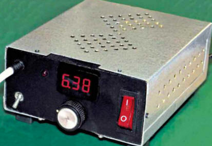
The manufactured power supply has a compact design, all parts are placed in a ready-made case with dimensions 129x114x47 mm made of 1 mm thick brass sheet (Fig. 2). The case is also used as an effective heat sink. Plastic legs about 10 mm high are attached to it, which is necessary for better air flow around it, and therefore for better cooling. The case does not have a direct electrical connection to the common wire of the power supply, but is connected to it by the R3C1R4 circuit to equalize potentials. The front panel of the unit is made of polystyrene sheet.
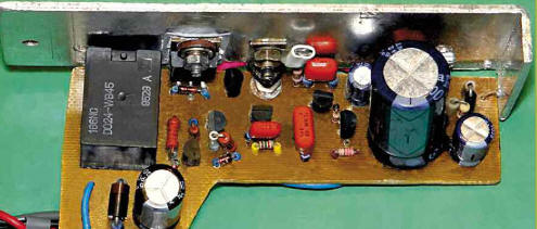
Since almost half of the volume of the case is occupied by the T1 transformer, the arrangement of the remaining elements of the device inside it is quite dense. The rectifier assembly on the VD3 diode bridge is assembled on a separate circuit board, shown in fig. 3. It also contains capacitors C2, C3, C7, C8, C10, resistor R13, diodes VD5-VD8 and resettable fuses. The remaining nodes are located on the board shown in Fig. 4.
Mounting boards double-sided hinged. All circuits through which a significant current flows are made with a mounting wire with a cross section of 0,75 mm2. For low-power circuits, an MGTF wire with a cross section of 0,03 mm2 is used. The wire going to the variable resistor motor is shielded, and those wires that are energized at 220 V are double insulated. After checking the operability of the device, the circuit boards on the side of the connections are varnished XB-784 to prevent accidental short circuits and increase the mechanical strength of the installation. Resistor R1 is a non-flammable discontinuous one, it can be replaced by a 0,5 A fusible link. The rest of the fixed resistors are MLT, RPM, C1-4, C1-14, C2-23 and other similar ones. Variable resistor R20 - SP4-1, but can be replaced by RP1-73a, SP3-9a, SP-04a. When using a variable resistor, the resistance of which differs from that indicated in the diagram (it can reach 2,2 kOhm), you will need to proportionally change the values of the resistors R17 and R19. Keep in mind that smaller variable resistors are usually more reliable. The varistor MYG20-471 (RU1) used in the device can be replaced by MYG20-431, FNR-20K431, FNR-20K471, GNR20D431K. The case of the varistor is covered with a fiberglass cover. Capacitors C5 and C6 are ceramic for surface mounting. Oxide capacitors - imported analogues of K50-68. The remaining capacitors are small-sized film capacitors. Diodes 1N4148 can be replaced by any of 1N914, 1SS244, KD510, KD521, KD522, and diode 1N4004 - from series 1 N4001 - 1N4007, UF4001 - UF4007, KD209, KD243, KD247. Instead of the EGP20A diode, 1N5401 - 1N5408, FR301 - FR307, diodes of the KD226, KD257 series are suitable, and instead of the Schottky diode 1 N5819 - SB140, SB150. Diode bridge RBV-406H can be replaced by any of FBU4, KBU6, BR605, KVRS601-KVRS610, RS801-RS807, KBU8. Before fastening to the brass body of the block, the surface of the bridge pressed against it must be lubricated with heat-conducting paste. Zener diodes 1N4738A are replaced by BZV55C8V2, TZMC8V2. Instead of the zener diode 1N4736A, BZV55C6V8, TZMC6V8 will do. LED HL1 can be of any type and color of glow. The TL431CLP chip can be replaced with AZ431AZ, LM431ACZ. The IRLZ44N transistor in this design can be replaced with IRL2505N, IRL3205, STP65NF06. At the time of assembly of the structure, its conclusions are connected by a wire jumper. Through an insulating gasket, the transistor is mounted on an aluminum plate measuring 125x35x2 mm. This plate is then screwed to the brass body of the device using thermally conductive paste. It should be noted that mounting the transistor in the TO-220 package on a heat sink through an insulating gasket limits its allowable maximum continuous power dissipation to approximately 30 watts. This should be taken into account when making a power supply with a higher power. You can increase it by connecting several field-effect transistors in parallel and using a more powerful transformer. The 2SD1616 transistor can be replaced with an SS8550, 2SC2331 or KT961 series with a base current transfer ratio of at least 50. Instead of 2SA733 transistors, 2SA709, SS9012, KT6115, KT3107 series transistors are suitable. Replacing the transistor 2SC945 - SS9013, SS9014, 2SC1815, KT3102 series. The power supply uses a relay found in a faulty washing machine. It is designed to operate at a voltage of 12 V on the winding, but it works at a much lower voltage. The measured winding resistance is 440 ohms. To replace it, any relay with approximately the same winding resistance and with a switching group of contacts capable of switching a current of at least 3 A and operating at a voltage of not more than 6 V is suitable. For use in the power supply, the mains toroidal transformer from the tape reverb "Echo-1" has been redesigned. All secondary windings and the winding screen have been removed from it. Four layers of PVC tape are added over the primary paper insulation. Winding 5-6-7 is wound with a bundle of six winding wires with a diameter of 0,39 mm each, twisted with an electric drill. It is necessary to prepare about 25 m of the harness. Winding on a toroidal magnetic circuit is carried out turn to turn with the help of a homemade shuttle. In section 5-6, 123 turns should be wound, and in section 6-7 - 150. After winding each layer, it is covered with a layer of paper tape, which is then impregnated with insulating varnish. Winding 3-4 contains 60 turns of winding wire with a diameter of 0,43 mm. Both secondary windings are laid with maximum effort so that they fit snugly against the magnetic circuit. You can use another transformer with an overall power of at least 30 VA, the secondary winding of which, used as a winding 5-6-7, is designed for a current of at least 1,3 A.
As a voltmeter PV1, a digital built-in device V20D-T1 was used (Fig. 5). It was purchased from one of the online stores for an amount (including shipping) less than the price of a conventional three-digit LED indicator. The voltmeter measures a constant voltage from 3,2 to 30 V with a current consumption of about 20 mA. The finished block starts working immediately. If necessary, by selecting resistors R17 and R19, you can set the desired upper and lower limits for adjusting the output voltage. Literature
Author: A. Butov
Machine for thinning flowers in gardens
02.05.2024 Advanced Infrared Microscope
02.05.2024 Air trap for insects
01.05.2024
▪ German cities may ban diesel cars ▪ IKEA DIRIGER smart home control center ▪ An affordable way to prevent caries
▪ section of the site Note to the student. Article selection ▪ article Strange and Strange. Popular expression ▪ article Why was the moon only half known for a long time? Detailed answer ▪ article Head of the expedition. Job description ▪ article Simple anti-theft devices. Encyclopedia of radio electronics and electrical engineering
Home page | Library | Articles | Website map | Site Reviews
www.diagram.com.ua |


 Leave your comment on this article: