|
|


 Arabic
 Bengali
 Chinese
 English
 French
 German
 Hebrew
 Hindi
Hindi Italian
 Japanese
 Korean
 Malay
Malay Polish
 Portuguese
 Spanish
 Turkish
 Ukrainian
 Vietnamese
|
ENCYCLOPEDIA OF RADIO ELECTRONICS AND ELECTRICAL ENGINEERING Charging the battery from the Peltier elements. Encyclopedia of radio electronics and electrical engineering
Encyclopedia of radio electronics and electrical engineering / Power Supplies The output voltage of a thermoelectric generator based on Peltier elements depends on temperature conditions and load. In the proposed design, the operating mode of the converter of this voltage to the one necessary for charging the lead-acid battery is automatically maintained in such a way that the generator always delivers the maximum possible power. This allows you to get the maximum amount of energy from the generator and store in the battery. It is known that in order to obtain the maximum amount of energy in the external circuit, it is necessary that the load resistance of the generator is equal to its internal resistance, and the latter of the Peltier element depends on the operating conditions. Since it is problematic to provide the same conditions for heating a large number of elements and removing heat from them, the way out is to divide their entire set into separate groups with approximately the same characteristics and thermal conditions. In this case, the optimal load is provided separately for each group. According to this principle, the device under consideration was built, consisting of two identical channels operating on a common load - a rechargeable battery. Main technical parameters
The scheme of the device is shown in fig. 1. Thermoelectric generators G1 and G2 are connected to the inputs of two identical conversion channels. Each channel is a step-up pulse voltage converter based on a storage inductor L1 (L2) and a powerful field-effect transistor VT3 (VT4), controlled by pulse-width modulation. The DD1 microprocessor (ATmega88-20AU) controls the operation of the converters. The codes from the TERMPR.hex file attached to the article must be loaded into its FLASH memory. The configuration of the microcontroller is programmed in accordance with the table, where the values of the digits are highlighted in color, which differ from those set by the manufacturer of the microcircuit.
On fig. 2 shows a diagram of voltage changes at the output of a thermoelectric generator of one channel during the working cycle of the device. The scale on the time axis is not respected. The cycle begins with the suspension of the converter at time t0, after which the generator voltage rises to the idle voltage Uxx, which, at the end of the transient process, the microcontroller measures in time tamended. At time t1 the microcontroller turns on the converter and in several stages changes the duration of the pulses controlling it, each time measuring the voltage of the generator. After another change in the duration of the pulses, the generator voltage enters the zone centered near U = 0,5Uxx (in this case, this is the moment t4). This corresponds to the optimal load on the generator, so the converter continues to operate at the set pulse width until, due to a change in conditions, the generator voltage goes beyond the ΔU zone. Then the process is repeated.
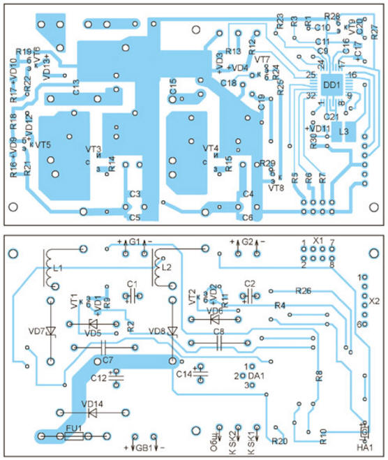
This is how the GB1 battery is charged. When the battery voltage reaches approximately 14 V, the charging current is reduced to prevent overcharging. The device enters the battery voltage stabilization mode. The microcontroller DD1 can be powered both from the battery GB1 through the integral stabilizer DA1, and from the thermogenerators G1 and G2 through current stabilizers on transistors VT5 and VT6. Thanks to this power organization, there is voltage at the terminals for connecting the battery even in its absence. It is enough for at least one thermogenerator to work. If the voltage of both thermogenerators has dropped below the minimum value, the DD1 microcontroller goes into sleep mode, after closing the transistors VT7 and VT8 and thus turning off the stabilizer DA1. In this case, the current consumption from the battery (if connected) is reduced to 0,4 mA. As soon as the voltage of at least one generator becomes higher than the minimum (approximately 3 V), the microcontroller "wakes up", turns on the DA1 stabilizer and controls the converters, as described above. If the generator idle voltage exceeds the battery voltage, then the battery is directly charged through the VD7 or VD8 diode and it becomes impossible to set the optimal load mode. Hence the limitation on the maximum voltage of the thermogenerator. LEDs HL1-HL3 are used to signal, respectively, the inclusion of the device and the operation of the voltage converters of the generators G1 and G2. An alarm is provided for overheating of thermogenerators - a sound signal is emitted by the HA1 sound emitter and the LED flashes. The temperature of each of the generators is controlled by thermal switches SK1 and SK2 with a response temperature of +120 оC. The most common and cheap Peltier elements can be operated at temperatures up to +138 оC. If you use high-temperature elements, then you need to use other thermal switches or abandon them altogether. A drawing of the printed circuit board of the device is shown in fig. 3, and the placement of elements on it - in Fig. 4. Many of the parts needed to make the device can be found on an unnecessary motherboard from a computer. For example, ARM2014N field-effect transistors are used in voltage converters to power the processor and memory on ASUS boards. Field-effect transistors STB70NF3LL are also well suited. The main requirement for these transistors is the threshold voltage not higher than 1,5 V (preferably 1 V). The use of devices with a higher threshold voltage leads either to their excessive heating, or the converter does not work at all, since the transistors do not open with the available voltage.
Chokes L1 and L2 are also made from those found on the motherboard. Their magnetic circuits were used - ferrite rings with dimensions of 15x8x6 mm. They are wound on 15 turns of wire with a diameter of 1 mm. Instead of diodes VS80SQ040 and BAS86, other Schottky diodes can be used, respectively, 40 V, 10 A and 40 V, 0,1 A. The microcontroller program can be downloaded from ftp://ftp.radio.ru/pub/2014/06/tempr.zip Authors: S. Tkachuk
Machine for thinning flowers in gardens
02.05.2024 Advanced Infrared Microscope
02.05.2024 Air trap for insects
01.05.2024
▪ Bicycle stabilization system ▪ LeTV X1 door lock with 3D face ID ▪ The danger of extinction of insects ▪ A new way to generate electricity with water
▪ section of the site Voltage stabilizers. Article selection ▪ Article Hospital Pediatrics. Lecture notes ▪ article Can fish hear? Detailed answer ▪ article Electrician. Standard instruction on labor protection ▪ article Focus with three cards. Focus secret
Home page | Library | Articles | Website map | Site Reviews
www.diagram.com.ua |


 Leave your comment on this article: