|
|


 Arabic
 Bengali
 Chinese
 English
 French
 German
 Hebrew
 Hindi
Hindi Italian
 Japanese
 Korean
 Malay
Malay Polish
 Portuguese
 Spanish
 Turkish
 Ukrainian
 Vietnamese
|
ENCYCLOPEDIA OF RADIO ELECTRONICS AND ELECTRICAL ENGINEERING Contactless charger for radio receiver. Encyclopedia of radio electronics and electrical engineering
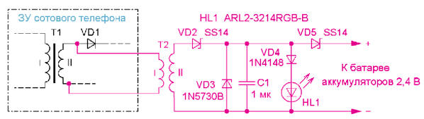
Encyclopedia of radio electronics and electrical engineering / Chargers, batteries, galvanic cells The article proposes a variant of a contactless charger based on a cell phone charger for a small-sized radio receiver. For greater convenience in charging batteries in small handheld devices such as radios, a contactless method can be used. This requires a pulse generator, to the output of which is connected the so-called "transmitting" coil. The radio receiver will require the installation of a "receiving" coil, a rectifier and display elements. When the coils are placed close to each other, they form a transformer, the energy from the first goes to the second and is then used to charge the battery. The so-called wireless chargers work on this principle (although, of course, they cannot do without wires), which are being used more and more widely. Descriptions of contactless chargers for flashlights were published earlier in the journal [1, 2]. They used a generator from the electronic ballast of a compact fluorescent lamp as a pulse generator. But a standard cell phone charger is also suitable as such a generator, if, of course, it is assembled according to the circuit of a pulse voltage converter. The contactless memory circuit is shown in fig. 1. For example, it was built into a small VHF FM radio receiver powered by two AAA galvanic cells. This radio receiver has enough space to accommodate the secondary winding of the T2 transformer and the remaining elements of the charger. The primary winding of this transformer is connected to the output winding of the pulse transformer T1 of the cell phone charger to the rectifier on the diode VD1. All pulse memory devices have a built-in DC output voltage stabilization unit. Therefore, the amplitude of the pulses on the secondary winding of the transformer T1, and hence on the primary winding of the transformer T2, will be stable.
The voltage pulses of the secondary winding of the transformer T2 are rectified by the diode VD2, and the ripple of the rectified voltage is smoothed by the capacitor C1. Zener diode VD3 limits the voltage at the output of the rectifier. Diode VD5 prevents the battery from discharging through the memory cells. The battery charging indicator is a flashing three-color LED HL1 [3]. When the battery is low, there is not enough voltage on the LED to turn on all of its crystals and only red and dim green flash. As the battery charges, the voltage rises, and when it reaches the nominal value, the blue flashes. By installing a VD4 diode (two or three silicon or Schottky), you can change the voltage at which certain crystals flash. The secondary ("receiving") coil of the transformer T2 contains 25 ... 30 turns of wire PEV-2 0,1. It is wound on a rectangular mandrel measuring 12x45 mm and placed inside the radio receiver housing on its rear wall - where there is no battery cover, and then fixed with hot glue (Fig. 2). The HL1 LED is installed in a hole in the housing, and the rest of the elements are soldered to its terminals. After checking and adjusting, they are fixed with hot glue. A surface mount capacitor is used.
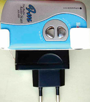
To fix the radio receiver on the body of the cell phone charger with the help of Moment glue, a clip holder made of springy plastic 1 mm thick was glued (Fig. 3). It covers the radio receiver and ensures its fixation in a position in which the coils of the transformer T2 will be opposite each other. The radio receiver is prevented from "failing" by its standard clip located on the rear wall.
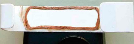
The holder contains the primary winding of the T2 transformer, containing 12 ... 15 turns of PEV-2 0,2 wire on the same mandrel (Fig. 4). The coil is glued with a small amount of glue "Moment" strictly opposite the coil of the secondary winding of this transformer. After adjustment, to protect against mechanical damage, it is covered with a thin layer of epoxy glue.
Before mounting the coils of the T2 transformer and other elements of the charger, a preliminary check and adjustment should be carried out. To begin with, the primary winding coil of the transformer T1 is connected to the output of the transformer T2 and the operation of the charger is observed. Within 10 ... 15 minutes it should not get very hot. Then, the rest of the memory elements (temporarily without an LED) are installed on the breadboard or by surface mounting and the windings of the T2 transformer are placed one above the other through a plastic gasket with a thickness equal to the thickness of the rear wall of the radio receiver housing. Connect the battery to the charger and measure the charging current. Since there are two options for connecting the primary winding of transformer T2 to the output transformer T1, choose the one in which the charging current is greater. By selecting the number of turns of the primary and secondary windings (within ± 2.3 turns), the required current is achieved. Then, by connecting a discharged battery, by selecting the number and types of diodes connected in series with the VD4 diode, the crystals of red and green colors are blinking. When a fully charged battery is connected, all crystals should flash, and the brightness of their flashes is remembered in order to then determine the degree of charge from them. If it is planned to embed such a memory in other devices, it must be borne in mind that with a decrease in the diameter of the coils, the number of turns must be increased, and vice versa. In addition, the cover on which the "receiver" coil is installed must not be conductive (metal or metallized). A video illustrating the operation of the device can be found at ftp://ftp.radio.ru/pub/2015/09/zu.zip. Literature
Author: I. Nechaev
Air trap for insects
01.05.2024 The threat of space debris to the Earth's magnetic field
01.05.2024 Solidification of bulk substances
30.04.2024
▪ The nurses will scrub the copper ▪ New multi-standard TV audio processors and audio demodulators ▪ Sony MDR-HW9.1DS 700 Wireless Headphones ▪ Spray instead of solar panels
▪ site section Spectacular tricks and their clues. Article selection ▪ article Alert to the civilian population. Basics of safe life ▪ article Where and when were foxes domesticated? Detailed answer ▪ article Electrician on secondary circuits. Job description ▪ article Four robbers. Focus Secret
Home page | Library | Articles | Website map | Site Reviews
www.diagram.com.ua |


 Leave your comment on this article: