|
|


 Arabic
 Bengali
 Chinese
 English
 French
 German
 Hebrew
 Hindi
Hindi Italian
 Japanese
 Korean
 Malay
Malay Polish
 Portuguese
 Spanish
 Turkish
 Ukrainian
 Vietnamese
|
ENCYCLOPEDIA OF RADIO ELECTRONICS AND ELECTRICAL ENGINEERING Power supply on a UCC28810 chip for a 18...48 W LED lamp. Encyclopedia of radio electronics and electrical engineering
Encyclopedia of radio electronics and electrical engineering / Power Supplies The author offers readers two options for a power source for LED lamps (they are also called LED drivers), one of them - the second - in many respects can be attributed to high-class (premium) sources. Over the past few years, the LED has become, without a doubt, the most popular light source, increasingly replacing other types. So, if earlier the LED was associated with an indicator device and was familiar mainly to technical specialists, then today, this word has become commonplace and almost synonymous with an ordinary incandescent lamp. And this is not surprising, because as soon as modern technologies made it possible to obtain and put into mass production white LEDs with a light output of more than 100 lm / W, which is more than ten times higher than that of an incandescent lamp and two to three times a compact fluorescent lamp, the issue of saving energy resources received a new solution. This is what developers and manufacturers of lighting devices around the world did not fail to take advantage of, filling the market with LED "analogues" of all existing types of lamps and fixtures with incredible speed. In addition, LEDs, due to their high manufacturability and reliability, small dimensions, etc., make it possible to create light sources of a wide variety of shapes, sizes, designs and purposes, offering ever new economical solutions. And one of the most massive applications of LED lighting is office ceiling lights with a power ranging from approximately 18 to 48 watts. They are now equipped with both new facilities under construction and existing ones, replacing the park of obsolete fluorescent lamps. Any LED lamp can be conditionally divided into two components: the LEDs themselves and the power source - a source of stabilized current, often called a driver, LED-driver (English) for them. Both of them equally determine the technical characteristics, quality and price of the lamp. If the LED determines the luminous flux and color temperature, then no less important parameters depend on its power source, such as the pulsation coefficient of the luminous flux, the power consumption factor, etc. Yes, and the reliability of an LED lamp is mainly determined by the reliability of its power source. Now the market offers the widest range of ready-made luminaires, as well as LED modules and power supplies for them separately. After a comparative analysis of several dozen models of power supplies up to 50 W (controlled and with a control function - dimming - were not considered) from various manufacturers, including domestic ones, a generalized list of the main parameters that a high-quality LED driver should have, which can be attributed to the premium class:
In this article, I would like to share some experience in developing a power source that meets the above requirements, as well as give an example of a simple conversion of an old fluorescent lamp to LED. The output voltage interval is selected within 60...120 V. The output current adjustment interval is within 240...350 mA, which makes it possible to connect most common LED strips. There can be many options for circuit solutions for solving such a problem. But the most common and obvious here is a flyback converter with galvanic isolation (called fly-back in foreign literature). There is a huge number of specialized microcircuits for building such a converter, at least several dozen families. And you can make a choice in favor of any particular microcircuit, based, at times, only on personal sympathies. In amateur radio practice, the choice is often made based only on the price and availability of the chip. Also, a very weighty argument when choosing is the presence on the manufacturer's website of the necessary reference information and, preferably, examples of the use of a particular microcircuit. In our case, the choice fell on the UCC28810D chip. This microcircuit is, in fact, a universal PWM controller for a switching power supply, it can be used to assemble both flyback and forward converters, step-down and step-up. Also, an important advantage of the microcircuit is the presence of a built-in power consumption correction function. This allows you to implement converters with a power consumption factor (PF - Power Factor) of at least 0,9 without the use of an additional corrector. A complete description of the microcircuit can be found, for example, in [1]. There, on the manufacturer's website (Texas Instruments), there are a large number of ready-made examples (reference designs) of power supplies using the UCC28810D, designed for LED lighting, which greatly facilitated the development process. In our case, the variant [2] is taken as a basis. Processing has undergone mainly the secondary part. A rather rare specialized TL103WD op amp has been replaced with a common and inexpensive LM258D, and the ability to adjust the output current has been added. The diagram of the resulting source is shown in fig. 1.
Consider briefly the main components and the principle of operation of the device. A current sensor is installed in the secondary circuit - resistors R22, R23. It is connected to the inputs of a DA2.1 differential amplifier with a gain of 37,5. Next, the amplified signal is fed to the inverting input of the op-amp DA2.2. An exemplary voltage is supplied to its non-inverting input from an adjustable source on a parallel stabilizer DA3. OA DA2.2 performs the function of a comparator. As soon as the voltage at the inverting input exceeds the reference level (at the non-inverting input), the voltage at the DA2.2 output drops to zero and the optocoupler U1 opens. As a result, the DA1 chip will reduce the open time of the transistor VT2 and the current through the load will decrease to the set value. Using the variable resistor R27, you can adjust the exemplary voltage at the non-inverting input of the DA2.2 comparator and, accordingly, the current through the load (LEDs). For example, with a load current of 350 mA, the voltage at the non-inverting input DA2.2 is about 3,5 V, approximately in the middle position of the resistor R27 slider. When the output voltage exceeds 125 ... 128 V, for example, in idle mode, the composite zener diode VD14-VD16 will open and the comparator DA2.2 will also open the optocoupler U1, and the DA1 chip will reduce the open time of the transistor VT2. A stabilized (3 V) power supply for the op-amp and optocouplers is assembled on the VT4 transistor and the adjustable reference voltage source DA11,8. The DA1 chip is powered at the moment of switching on through resistors R7, R8. In steady state, the microcircuit is powered by an additional winding of the transformer T1 through a stabilizer on the transistor VT1. The same winding is connected through resistors R13, R16 to the TZE input (pin 5) DA1, which serves to control the moment of zero energy of the transformer T1, which is necessary to determine the moment of the next opening of the transistor VT2. A complete description and principle of operation of the UCC28810D chip can be found in [1]. The described power supply after assembly, adjustment and testing showed the following Features:
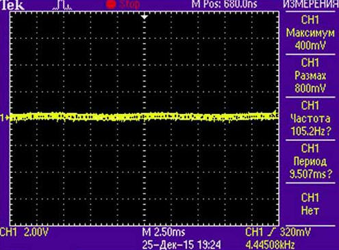
It follows from them that, contrary to expectations, the source does not meet one of the most important requirements given at the beginning of the article - the pulsation coefficient of the light flux. The resulting value of 12% also does not comply with the sanitary and epidemiological rules and regulations [3] for the lighting of rooms intended for working at a computer (should be no more than 5%), but it is quite suitable, for example, for street lighting, a warehouse, a gym and etc. The pulsation coefficient of the luminous flux was measured with a TKA-PKM (08) luxmeter when a load was connected in the form of four series-connected LED lines with a total power of 42 W and a current consumption of 350 mA. On the oscilloscope (Fig. 2), these ripples appear as a 100 Hz hum with a swing of only 3,6 V at a constant level of about 100 V (the oscilloscope input is in AC voltage mode).
Since a lot of time was spent on development (calculation of some elements, board routing, assembly, etc.), it was decided to refine the device and still achieve compliance with all requirements. The easiest way to reduce the ripple is to increase the capacitance of the smoothing capacitor C16. When it was increased from 330 to 1000 microfarads (three 330 microfarad capacitors connected in parallel at 160 V), the luminous flux ripple coefficient fell below 5%, which is good, but still not enough. In addition, the dimensions of the entire device have almost doubled, and the cost of high-voltage oxide capacitors is not small. A much better result is obtained by increasing the capacitance of the capacitor C8. When replacing the film capacitor C8 with an oxide capacitance of 47 μF, the luminous flux ripple coefficient of the lamp decreased to the desired 1%. But in this case, what is expected, another problem arises - the power consumption factor decreases from 0,95 to 0,5. This happens due to a significant increase in the capacitive component of the driver input resistance, in other words, the device turns into a capacitive load for the network. A completely logical solution in this case is to include an active power factor corrector between the noise input filter and the converter. You can, of course, use a simpler passive corrector, but its effectiveness is much lower. Such a refinement significantly increases the total number of elements and complicates the device, but the main task is to achieve the declared performance, so it was decided to use this option. The scheme of differences of the modified device is shown in fig. 3. The numbering of elements continues the one started in fig. 1. The power factor corrector assembly is connected to the break in the positive power wire, indicated in the diagram in fig. 1 cross. In addition, a 1 nF capacitor (C29) and a 1 MΩ resistor with a power of 0,25 W (R55) are installed in parallel with the output. Diodes VD1, VD2 were removed (see Fig. 1), in series with resistors R1 and R2 (with a power of 0,125 W), another one with a resistance of 1 MΩ with a power of 0,125 W was installed (marked as R54 on the board), one of its outputs is connected to the top output according to the circuit resistor R1, and the other is connected to the cathode of the VD19 diode (Fig. 3). Capacitors are connected between terminals 1 and 3 of stabilizers DA3 and DA4: between terminals DA3 with a capacity of 1 nF (C27), DA4 - 10 nF (C28). In parallel with the capacitor C20 with a capacity of 4,7 μF (instead of 0,1 μF), another one of the same capacity (4,7 μF) is installed.
In addition, the values of some elements have been changed. The capacitance of the capacitor C1 is increased to 0,2 μF, s1 1 - up to 4,7 μF, C17 - up to 0,1 μF, C8 - reduced to 0,1 μF, C16 - up to 100 μF, C18 - up to 0,047 μF, C19 - up to 2,2 uF, C9 - 150 pF, the oxide capacitor C6 is replaced by a ceramic capacitance of 4,7 uF. Resistors R22, R23 (current sensor) are replaced by one 1 ohm resistance with a power of 1 W. The resistance of the resistor R17 is 1 ohm, the dissipation power is 0,25 watts. Instead of two resistors connected in parallel (R18, R19), one of the same power with a resistance of 1 ohm is installed. Resistor resistance R3 - 13 kOhm, R4 - 10 kOhm, R7 and R8 - 120 kOhm, R20 and R24 - 1,8 kOhm, R21 and R25 - 36 kOhm, R26 - 10 Ohm. Zener diode BZV55C51 (VD16) has been replaced by BZV55C18, and BZV55C15 (VD8) by BZV55C18. Instead of the HS2K (VD11) diode, HS1J is used. The active power corrector is made on a specialized L6561D (DA5) microcircuit. The principle of operation of a typical active power corrector is illustrated by the graph in fig. 4. When the transistor VT4 is open, the primary winding of the transformer T2 is connected to the output of the diode bridge VD3-VD6, and energy is accumulated in it. At this time, the capacitor C26 serves as the power source for the rest of the device. When the current through the primary winding reaches its maximum value, the transistor VT4 closes, and the transformer T2 begins to give all the accumulated energy through the diode VD19 to the capacitor C26. This process is repeated many times (the sawtooth current through the primary winding T2 is shown in the graph in red) for the half-cycle of the mains voltage (blue curve in the graph), as a result, the shape of the average current consumed is close to sinusoidal (shown in green). The frequency of the control pulses is determined by the DA5 chip, it depends on the instantaneous value of the mains voltage and the discharge rate of the capacitor C26. With the help of the divider R49-R53 connected to the INV input (pin 1) DA5, a voltage of 390 V is set at the output of the corrector. The R40-R43 divider connected to the MULT input (pin 3) DA5 sets the operating voltage interval of the network, in our case, the corrector maintains a constant level of 390 V on the capacitor C26 in the input voltage range from 90 to 265 V. The corrector is powered through the VD20 diode from a stabilized source on the transistor VT1 (see Fig. 1). In this regard, it starts working only after the flyback converter is started. Input CS (pin 4) DA5 is used to control the current through the transistor VT4. From the GD output (pin 7), the control pulses are fed to the gate of the transistor VT4. The ZCD input (pin 5) of the microcircuit serves to determine the moment when the current through the transformer decreases to almost zero. A more detailed description of the operation of the microcircuit is given in [4].
The second driver option has the following Features:
As you can see, the second option meets all the requirements. A small disadvantage can be considered a lower efficiency. The oscillogram of the variable component (ripples) of the output voltage is shown in fig. 5. For clarity, the settings of the oscilloscope and the LED load were the same as for fig. 2. The same load was used when taking the following oscillograms: in fig. 6 upper (green) waveform - voltage at the drain of the transistor VT2, lower (yellow) - at the gate; in fig. 7 top (green) - on the drain of the transistor VT4, bottom (yellow) - on the gate.
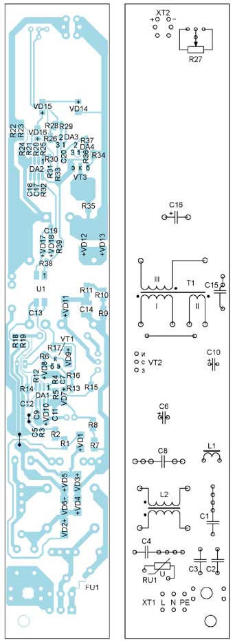
The printed circuit boards are designed for both options. The board drawing for the first option is shown in fig. 8, the location of the elements - in fig. 9, for the second - in fig. 10, the location of the elements - in fig. eleven . The boards are made of FR-11 fiberglass laminated on one side. All elements for surface mounting are located on the side of the printed conductors, output - on the opposite side.
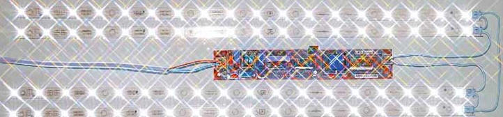
The inductor of the noise suppression filter L2 is wound on an E19/8/5 (Epcos) magnetic circuit and has an inductance of 350 mH, each winding contains 130 turns of wire with a diameter of 0,25 mm. The inductor L1 is a standard dumbbell-shaped inductance of 3 mH, designed for a current of at least 0,3 A. The transformer T1 in both versions of the driver is the same and is made on the magnetic core E25/13/7 (Epcos) of N27 material with a gap of 0,5 mm. The primary winding (I) consists of two parts and contains 47 + 22 turns of a two-core wire, the core diameter is 0,3 mm. The inductance of the primary winding is 0,7 mH. The secondary winding (III) contains 53 turns of a three-core wire, the core diameter is 0,3 mm. Additional winding II contains 13 turns of a single-core wire with a diameter of 0,3 mm. The order of the windings is as follows: first, the first part of the primary winding is wound - 47 turns, then the secondary, then the second part of the primary - 22 turns and the topmost - additional winding. The power corrector transformer has the same magnetic circuit with the same gap. Its primary winding contains 175 turns of a single-core wire with a diameter of 0,3 mm, the secondary - 7 turns. The inductance of the primary winding is 2,5 mH. Resistors R20-R26, R28-R37 are preferably used with a tolerance of 1%, the rest - 10%. Surface mount capacitors for the second version of the driver C5, C7, C9, C12, C13, C17, C18, C22, C28 - size 0603, C6, C11, C19, C20, C21, C23, C24, C27 - size 0805, C30 - size 1206. Surface mount capacitors for the first version of the driver C5, C7, C9, C12, C13, C17, C18 - size 0603, C11, C19, C20 - size 0805. C14 (for both options) - high-voltage (for a rated voltage of 630 C) size 1812. High-speed diodes of the HS2 and MURS160 series can be replaced with similar ones, LL4148 - with any pulse diodes with a reverse voltage of at least 50 V. Transistors MMBT2222ALT1, STP5NK80Z and PZTA42 can also be replaced with analogues. In the first version, STP5NK80Z (VT2) can be replaced with a lower voltage one, for example STP5NK60Z. Resistors R18, R28 and R48 are not installed in parallel, places for them on the board are provided for fine tuning. The device is mounted in a suitably sized tin case from an electronic ballast of a fluorescent lamp; an insulating gasket is also used from it, in which it is necessary to wrap the driver board before installing it into the case. Transistor VT2 must be attached to the metal wall of the housing with a screw or with a bracket. This heat sink is quite enough for a load power of 35 to 50 W, while the transistor does not heat up above 50 оC, in the case of lower power, a heat sink is not needed. When operating a driver without a metal case with a load of more than 35 W, any standard small-sized heat sink must be attached to the VT2 transistor. The case for the driver is easy to bend, for example, from the case of a computer power supply, an insulating film is also suitable from it. In total, ten copies of the driver variant with a power corrector were manufactured (see Fig. 3), the first five of them have already successfully worked for more than six months with a maximum load of 50 W. Photos of the assembled board of the second version of the device are shown in fig. 12, fig. 13 - with a connected load (in the photo of Fig. 12, a "star" filter is used). The NEO-L-18R2834_520 LED strips of the domestic manufacturer "NEON-EK" were used as a load. Each string contains 18 SEL-WW2835-3K LEDs that are connected in three parallel strings of six LEDs in series.
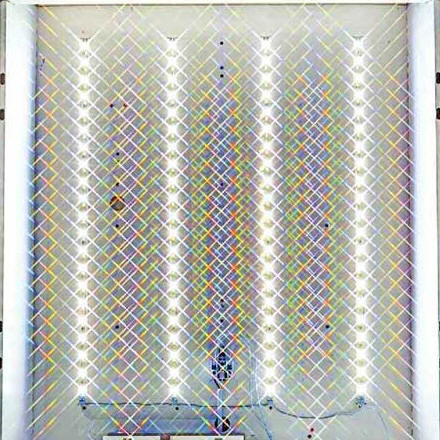
A properly assembled device starts working immediately and does not need to be adjusted, but it is still better and safer to run the driver in stages. Let's start with the second part. To do this, you need a laboratory power supply with an output voltage of at least 15 ... 20 V, capable of delivering current up to 500 mA. It is connected in parallel with the capacitor C16 and make sure that a voltage of 3 ... 11,6 V has appeared on the emitter of the transistor VT11,8. Then an ammeter and a load are connected to the output of the device. It is not necessary to use LED modules as a load, a powerful wire resistor of such resistance is also suitable so that the current is, for example, 300 mA. An ohmmeter or multimeter is connected to pins 3 and 4 of the U1 optocoupler in ohmmeter or continuity mode. The engine of the variable resistor R27 is set to the lower position according to the diagram (to the position of maximum resistance). Now, smoothly moving the resistor slider up, make sure that the optocoupler opens at a load current (ammeter reading) of 300 mA. The engine should be approximately in the middle. You can also check the opening of the optocoupler at different current values by changing the load resistance. Next, turn off the laboratory source, leave the load with the ammeter and proceed to check the flyback converter. The power corrector is first turned off - the VT4 transistor and the T2 transformer are soldered or its primary winding is closed (see Fig. 3). Connect the driver to a 230 V network, always through an incandescent lamp and another ammeter. If everything is in order, then at a load current of 300 mA and with a 95 W lamp, the current consumption should not exceed 210 mA, while the lamp should glow at about a third of the heat. They are convinced that the output current is regulated by the resistor R27 over the entire range: from 240 to 390 mA. And finally - they connect a power corrector - the lamp should start to shine a little brighter, but the total current consumption should not exceed 310 mA. You can, of course, check the power corrector separately by disconnecting it from the rest of the device. If everything went well, you can try to connect the driver to the network directly, without a lamp - with a network voltage of 230 V and a load current of 300 mA, the current consumed by the device should not exceed 140 mA. If an old fluorescent fixture is available, for example with four 18W lamps, it is easy to convert it into an energy efficient LED. From the old lamp, only its body is needed, everything else (lamps, starter, etc.) is removed. At the base of the housing, four or five of the previously mentioned LED strips are evenly placed. Further, holes are drilled in the right places and the rulers are riveted or screwed. It is desirable to rivet each ruler evenly in four places to ensure uniform heat dissipation. The driver is placed and fixed on the end side of the lamp. A variant of the resulting lamp is shown in Fig. 14 and fig. 15 (using a "star" filter).
If there is a desire and opportunity, you can install a diffuser made of polystyrene or polycarbonate. However, it should be borne in mind that the diffuser, of course, significantly improves the aesthetic qualities of the lamp, but no less worsens its light output. So, a relatively transparent diffuser "Opal" reduces the luminous flux by 30...40%! Literature
Author: V. Lazarev
Machine for thinning flowers in gardens
02.05.2024 Advanced Infrared Microscope
02.05.2024 Air trap for insects
01.05.2024
▪ The concentration of carbon in the air has reached a record high ▪ Acer to compete with Asustek in the budget laptop market
▪ section of the site Tips for radio amateurs. Selection of articles ▪ article About the dead - or good, or nothing. Popular expression ▪ article Why anti-drug propaganda on school pencils failed in New York? Detailed answer ▪ article Fitter for the installation of steel and reinforced concrete structures. Job description ▪ article AC protection device. Encyclopedia of radio electronics and electrical engineering
Home page | Library | Articles | Website map | Site Reviews
www.diagram.com.ua |


 Leave your comment on this article: