|
|


 Arabic
 Bengali
 Chinese
 English
 French
 German
 Hebrew
 Hindi
Hindi Italian
 Japanese
 Korean
 Malay
Malay Polish
 Portuguese
 Spanish
 Turkish
 Ukrainian
 Vietnamese
|
ENCYCLOPEDIA OF RADIO ELECTRONICS AND ELECTRICAL ENGINEERING Advanced power supply on the UCC28810 chip for LED lamps. Encyclopedia of radio electronics and electrical engineering
Encyclopedia of radio electronics and electrical engineering / Power Supplies In the author's article "Power supply on UCC28810 for LED lamp with a power of 18 ... 48 W", a power supply for an LED lamp was described, which has parameters that allow it to be classified as a high-class (premium) source. The author managed to upgrade the device, simplifying it, but leaving the parameters at a high level. A distinctive feature of the improved device is the use of an active current-measuring shunt. Continuing the popular topic of LED lighting, namely, power supplies for LED lamps, I would like to present another version of the LED driver based on the widespread UCC28810 chip [1]. This is a modified and simplified version of the source described in [2]. It was still decided to abandon the use of an additional active power corrector on the L6561D chip, which served mainly to power the UCC28810 chip with direct current, which made it possible to get rid of the output current ripple at a frequency of 100 Hz. In the proposed version, the problem of output current ripples, and consequently, luminous flux pulsations of the lamp, was solved by completely reworking the feedback unit - in fact, changing the principle of its operation, which also led to a significant simplification of the device by about a third. True, I had to sacrifice a little the technical characteristics of the power source: the input voltage interval narrowed and the power factor slightly decreased, but the luminous flux ripple factor remained at the same level - less than 1%. The diagram of the resulting source is shown in fig. 1.
Main Specifications
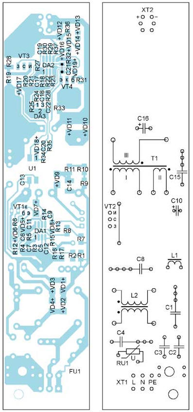
The primary part of the LED driver remained unchanged, except for the ratings of some elements. A distinctive feature of the secondary part is an active current-measuring shunt, which changes its resistance depending on the current flowing through it. Its resistance is formed by resistors R19, R26 and the channel resistance of the field effect transistor VT3. The total resistance of the shunt at a particular moment depends on the state of the transistor VT3. The comparator on the op amp DA2.1 controls its state, and, consequently, the total resistance of the shunt. The voltage drop from the shunt through the divider R29R32R37 and the protective zener diode VD16 is fed to the inverting input of the comparator on the op-amp DA2.2, which controls the optocoupler U1. The reference levels for both comparators are set by a common precision source on the DA3 parallel stabilizer. At the initial moment, there is a high level at the output of the comparator DA2.1, the transistor VT3 is open. The shunt resistance in this case is determined mainly by resistor R19, since the resistance of the transistor channel in the open state is only about 65 mΩ. Since the total resistance of the shunt is small, the voltage drop across it is small - less than the exemplary level at the non-inverting input DA2.2, therefore, the output of this comparator is high and the optocoupler is closed. As the current through the resistor R19 increases, the voltage drop across it will approach the threshold value, and when it is reached, the comparator DA2.1 will switch, its output will go low, the transistor VT3 will close. Immediately, the total resistance of the shunt will increase sharply - up to about 100 ohms (determined by resistor R26). The voltage instantly increased on the shunt will switch the comparator DA2.2, a low level will be set at its output, the optocoupler will open and the generation in the primary part of the converter will stop. Further, as the oxide capacitor C16 is discharged, the voltage drop across the resistor R19 will become below the threshold value, the comparator DA2.1 will return to its original state. Transistor VT3 will open, the total resistance of the shunt circuit will again sharply decrease to about 1 Ohm, the comparator DA2.2 will switch to its original state, the optocoupler will close, the generation will resume and the whole process will repeat cyclically. In fact, the node on the VT3 transistor and the DA2.1 comparator is a modification of the well-known electronic choke on a field-effect transistor. Only in our case, this electronic choke controls the operation of the entire flyback converter through an optocoupler. Using resistors R22, R23 connected in parallel, you can set any output current in the range from 290 to 390 mA. They, of course, can be replaced with one resistor of the appropriate resistance, for example, for an output current of 350 mA, instead of two 39 kΩ resistors, one with a resistance of 19,5 kΩ can be used. You can also use a small-sized tuning resistor. By selecting the resistor R3, if necessary, you can set the maximum value of the power factor. Resistors R3, R22, R23, R25 are preferably used with a tolerance of 1%. The 65C6600 field effect transistor (VT2) can be replaced with any other n-channel MOSFET with a drain-source voltage of at least 550 V, a current of at least 4 A and an on-state resistance of 1,5 Ω or less (for a transistor with a higher channel resistance, heatsink), suitable, for example, STP5NK60Z. The IRLL024NPBF (VT3) transistor in the SOT-223 package can be replaced with a similar low-voltage one with a drain-source voltage of at least 40 V, a current of at least 1,5 A and an open-state channel resistance of no more than 200 mOhm. All winding elements L1, L2, T1 are the same as in the prototype [2]. The printed circuit board is made of fiberglass laminated on one side; its drawing is shown in fig. 2. All elements for surface mounting are located on the side of the printed conductors, the output elements are on the opposite side. The arrangement of parts is shown in fig. 3. Photos of the assembled device are shown in fig. 4, fig. 5. The first start is best done, like any pulsed source, through a series-connected incandescent lamp.
Literature
Author: V. Lazarev
Machine for thinning flowers in gardens
02.05.2024 Advanced Infrared Microscope
02.05.2024 Air trap for insects
01.05.2024
▪ Miniature key component for a quantum computer ▪ Mindfulness enhances selfishness
▪ section of the site Encyclopedia of radio electronics and electrical engineering. Article selection ▪ article Fission reaction. History and essence of scientific discovery ▪ article Why is one of the proteins in the human eye named after Pikachu? Detailed answer ▪ article Work on the insert-sewing-cutting machines. Standard instruction on labor protection ▪ article Discoloration of ink and other dyes with activated carbon. Chemical experience
Home page | Library | Articles | Website map | Site Reviews
www.diagram.com.ua |


 Leave your comment on this article: