|
|


 Arabic
 Bengali
 Chinese
 English
 French
 German
 Hebrew
 Hindi
Hindi Italian
 Japanese
 Korean
 Malay
Malay Polish
 Portuguese
 Spanish
 Turkish
 Ukrainian
 Vietnamese
|
ENCYCLOPEDIA OF RADIO ELECTRONICS AND ELECTRICAL ENGINEERING Automatic battery charger. Encyclopedia of radio electronics and electrical engineering
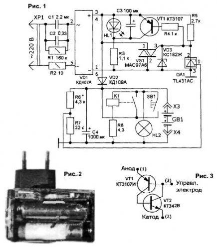
Encyclopedia of radio electronics and electrical engineering / Chargers, batteries, galvanic cells The developed automatic charger (AZU) allows you to charge small-sized and finger-type batteries of MP3 players. digital cameras, flashlights, etc. from the network. Its use allows you to abandon several chargers and produce a complete discharge of batteries in order to eliminate the "memory effect" that widespread nickel-cadmium (Ni-Cd) batteries have. The charger for batteries implements the RF utility model patent No. 49900 dated 04.08.2006. The charger from [1] served as a prototype for it. The main features of the automatic charger are provided by the use of an integrated circuit TL431 (adjustable zener diode) and the use of an alternator based on a reactive element (in this embodiment, a capacitor). Automatic charger provides charging "finger" batteries AAA and AA with a stable current of 155 mA from the mains (220 8, 50 Hz). It can also be used at lower mains voltages with a proportional reduction in the charging current. The stability of the charging current is entirely determined by the stability of Fig. 1 of the AC supply voltage. At the beginning of the battery charge, the signal LED lights up, before the end of charging, it starts flashing, and then turns off completely. The charger provides automatic reduction of the charging current (at least by an order of magnitude) when the EMF of the charged battery is reached and a light indication of this mode. In stand-alone mode (without connecting to the network), the battery is automatically discharged to a voltage of about 0,6 V with a light indication of the process. With a fully charged battery, such a discharge begins with a current of approximately 200 mA. The discharge of the entire battery of batteries is irrational, because. may be exacerbated by the non-identity of its constituent batteries. The device contains:
Capacitors C1 and C2 for AC are reactive ballasts and thus provide a current of approximately 155 mA. To discharge the capacitors after the device is turned off, resistor R1 is used, shunting the capacitors. Resistor R2 limits the amplitude of the inrush current when the charger is turned on and serves as a kind of fuse in case of a possible electrical breakdown of capacitors C1 or C2. Rectifies alternating current diode bridge VD1. The charger circuit is shown in Fig.1.
The main link in the control circuit is the microcircuit of the controlled zener diode DA1. It "opens" at a stable voltage of 2,5 V at control input 1, enabling the triac VS1 to turn on. The control voltage for DA1 is obtained from the battery voltage G81 across the resistor divider R1-R2. The divider is configured to charge the battery from two "finger-type" batteries. Capacitor C4 filters the voltage in the charge circuit and limits it during transient processes of charging capacitors C1, C2 (for example, when the AZU is turned on without load). When VS1 is opened, the entire battery charge current closes through it, the decoupling diode VD2 closes, and the power consumed by the charger from the network decreases. The LED HL1 of the indication circuit does not light up, indicating that the batteries are charged. These processes are repeated in each half-cycle of the supply voltage, therefore, to extinguish the flashes of the HL1 LED at the beginning of the half-cycles, a low-pass filter R3-C3 is used. The voltage at C3 does not have time to reach the voltage of the LED, and after the operation of DA1, the transistor VT1 turns on, discharging the capacitor C3. The Zener diode VD3 provides overvoltage protection at the input of the charge circuit (limits the voltage to 9 V), for example, in the event of a DA1 malfunction. The discharge circuit allows you to completely discharge and even in some cases restore Ni-Cd batteries, ensuring their operation without loss of capacity due to the "memory effect" [2]. In the same article, it is recommended to carry out such operations for individual batteries after about 30 cycles of operation. I note that the currently more common Ni-MH (nickel-metal hydride) batteries have a "memory effect", but to a much lesser extent. The discharge is made for one accumulator. Instead of the second battery, its short-circuited overall layout is installed for the duration of the discharge. The SB1 button is pressed, the HL2 lamp is connected to the battery, and the K1 relay is activated, the contacts of which block the button. The battery is discharging. When the voltage on the battery is about 0,6 V, relay K1 opens its contacts, and the battery is disconnected from the discharge circuit. Lamp HL2 provides an indication of the discharge, and also contributes to the stabilization of the discharge current. because as the voltage decreases, its resistance decreases. In principle, with the help of a charger it is possible to charge one completely discharged battery using an overall layout instead of a second one. To do this, it is necessary to control the charging time t in accordance with the dependence: 1=0.011С. (hour) where C is the battery capacity (mAh). For example, you need to charge a battery with a capacity of 1000 mAh. To do this, it must be connected using the AZU to the 220 V network for the time t=0,011 1000=11 (hour). Automation and AZU indication do not work in this case. The charger is assembled in the case of the charger from the mobile phone "Samsung A300" (Fig. 2). Holes with a diameter of 3 mm are drilled in the body to facilitate the thermal regime. A standard battery cassette for two AA batteries is glued to one of the sides of the case through a corner insert (to accommodate the discharge circuit). A new node with radio components is installed instead of the old one, and a ready-made hole (1 mm in diameter) in the case is used for the HL3 LED. The board for this assembly is made of thermoplastic plastic, such as vinyl plastic. Radio components are either glued to it, or their leads are fused into the board. All adhesive connections in the charger are made with 88HT adhesive. Installation - hinged. The self-made relay K1 is made on the basis of the KEM-2 reed switch (it works at 15 A-turn). A polyvinyl chloride tube is put on the body of the reed switch, over the entire length of which a winding of 1 turns is wound with a PEL-00,12 wire of 200 mm. Resistor R8 (Fig. 1) selects the release voltage of relay K1 within 0,6 ... 1 V. The charger uses resistors of the MPT-0,125 type (R1. R2 - MLT-0,25). film capacitors K73-17 for 250 V (C1. C2). 10 V oxide imported capacitors (C3, C4), baseless miniature incandescent pump 3 V / 0,1 A and a bright red LED with a diameter of 3 mm. Almost any silicon low-power transistors of general application can be used in the device. I could not find a thyristor controlled by an anode pn-junction, so I used a triac from Motorola (VS1). It can be successfully replaced by a transistor equivalent (Fig. 3). The replacement has been experimentally verified. A charger properly assembled from serviceable radio components only requires setting the DA1 operation voltage using resistor R6. The resistor is disconnected from the positive bus and a constant voltage of 2.9 V is applied from a separate source to the divider R6-R7 (Fig. 1). With the battery installed, the charger is connected to the mains and the resistance R6 is selected so that the DA1 chip starts to work (it is controlled by the glow of the HL1 LED or using an oscilloscope). After that, turn on R6 in place and finally assemble the structure. Elements C3. R4. VD3 and VT1 can be removed from the circuit without changing the electrical characteristics of the charger. because they only increase its reliability and ease of use (there is a better signaling of the end of battery charging). An exception is also possible for capacitor C2. This will slightly reduce the charge current. This is a universal charger. My version of the charger has been successfully operated for more than a year, including being used as a charger for the phone. For this, the necessary circuits are introduced into it. To charge smaller batteries, size AAA, the simplest adapters are used to ensure their contact in the charger. In addition, as already mentioned, a short-circuited overall layout of an AA battery is required to work with a single battery. Attention! The electrical circuits of the charger are connected to the 220 V network! When using the charger, make sure that no live circuits are touched! Literature
Author: V.Gustkov, Samara
Machine for thinning flowers in gardens
02.05.2024 Advanced Infrared Microscope
02.05.2024 Air trap for insects
01.05.2024
▪ Pleasure centers help the immune system ▪ Turbocharged GeForce RTX 3070 Ti Turbo graphics card
▪ site section Electrical work. Article selection ▪ article Cylinder coloring. Tips for the home master ▪ article Why was the nuclear explosion scene removed from the Diamond Arm? Detailed answer ▪ article Work on a milling machine. Standard instruction on labor protection ▪ article Phase preselector. Encyclopedia of radio electronics and electrical engineering
Home page | Library | Articles | Website map | Site Reviews
www.diagram.com.ua |

 Leave your comment on this article: