|
|


 Arabic
 Bengali
 Chinese
 English
 French
 German
 Hebrew
 Hindi
Hindi Italian
 Japanese
 Korean
 Malay
Malay Polish
 Portuguese
 Spanish
 Turkish
 Ukrainian
 Vietnamese
|
ENCYCLOPEDIA OF RADIO ELECTRONICS AND ELECTRICAL ENGINEERING Phase imbalance signaling device. Encyclopedia of radio electronics and electrical engineering
Encyclopedia of radio electronics and electrical engineering / Protection of equipment from emergency operation of the network, uninterruptible power supplies "Distortion" of the phases, i.e., the inequality of the phase voltages or the deviation of the phase shift between them from the nominal 120 ° - a malfunction of the three-phase electrical network, which can lead not only to a decrease in the power of the electric motor connected to it, but also to its dangerous overheating. The device described in the article will help to detect such a malfunction in time. Most of the devices for protecting the load from "distortion" of phases described in the literature contain three (according to the number of phases) rather complex voltage control channels and a logic node that generates an alarm signal. Meanwhile, there is a very simple way not only to detect "skew", but also to measure its magnitude. It is enough, according to the circuit shown in Fig. 1, to connect three resistors and an AC voltmeter.
If the resistances of the resistors R1-R3 are equal, the PV1 voltmeter connected between their connection point D and the neutral of the three-phase network will show the voltage UD = mUph / 3, where Uph is the rated phase voltage; m is the relative deviation of the voltage of one of the phases from the nominal value (it is assumed that the other two are exactly equal to the nominal value). The validity of the formula will remain even if m is the deviation of the phase difference from 120 °, expressed in radians, however, only if its value does not exceed 20 ... 30 ° in absolute value. When replacing the PV1 voltmeter (with an AC milliammeter, the readings of the latter will be equal to ID = mUf/R, where R=R1=R2=R3. Interestingly, both formulas remain correct if the resistors are replaced by capacitors of the same capacitance or coils of the same inductance. It is only necessary when calculating the current instead of the active resistance R to substitute the reactive capacitive Xc \u1d 2 / 2πfC or inductive XL \uXNUMXd XNUMXπfL, where f is the frequency of the alternating current. The diagram of the phase imbalance signaling device, built according to the described principle, is shown in fig. 2.
Here, each of those shown in Fig. 1 resistors are composed of two: main (R1-R3) and additional (R4-R6). For proper operation, it is necessary to fulfill the equality R1 + R4 \u2d R5 + R3 \u6d R1 + R3, therefore resistors (especially R1-R1) must be with a minimum (no more than ± 3%) permissible deviation of resistance from the nominal value or selected with such accuracy. Parallel to the additional resistors, the contacts of the buttons SB4-SB1 are connected. Pressing any of them simulates a phase "skew" of m = R4/(R5+R2), m = R5/(R6+R3) or m = R6/(R7+RXNUMX). This is used to check the health of the device or set the threshold for its operation using the trimmer resistor RXNUMX. The VD1VD2C2 rectifier converts the "skew" AC voltage into a DC voltage. Zener diode VD1 limits the rectified voltage with a large "skew". The voltage from the output of the rectifier is supplied to the signaling device itself - two multivibrators on the elements of the DD1 microcircuit. DD1.1), which generates bursts of pulses with a repetition rate of 1.2 ... 1 kHz. An intermittent signal sounds from the piezo emitter HA1.3. The frequency of the latter depends on the values of the elements C1.4, R2, and the frequency of repetition of packs - on C3 and R1. LED matrix HG1 - indicator of the presence of voltage in the network. The fact is that in its complete absence, the device does not give any sound signal, and such a situation can only be judged by the extinguished LEDs. They also allow you to quickly find the faulty phase, for example, in the event of a phase wire break. On fig. Figure 3 shows which LEDs of the matrix (connected in accordance with Fig. 2) correspond to phases A, B and C. The matrix is shown from the side of the LEDs (its pins 1-12 are on the reverse side).
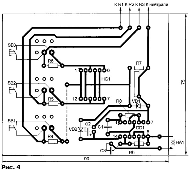
The signaling device is assembled on a printed circuit board (Fig. 4). Pushbutton switches SB1-SB3 - P2K without fixing in the pressed position, resistors - MLT, capacitors - K10-17-16 (C1, C3) and K50-35 (C2). Sound emitter HA1 - any piezoelectric, for example, ЗП-5. Since the resonant frequency of such emitters can be different, it is recommended to change the capacitance of the capacitor C3 to select the frequency of the generated signal according to the maximum volume.
Resistors R1-R3 are installed on the mounting plates in the immediate vicinity of the controlled electrical appliance and connected to the signaling device board with a four-wire cable. Instead of K561LA7, you can use the K561LE5 chip. The DLC/6SGD LED matrix can be replaced by the DLA/6SGD modification and matrices of the same series of a different glow color. Suitable and domestic KIPM20G-6L-12-1 or KIPM20E-6K1-12 (respectively, green and red glow). In an extreme case, you can use three pairs of single LEDs connected in anti-parallel. Author: A.Sergeev, Moscow
Machine for thinning flowers in gardens
02.05.2024 Advanced Infrared Microscope
02.05.2024 Air trap for insects
01.05.2024
▪ Red wine speeds up fat burning in the liver ▪ Touch screens will become cheaper
▪ section of the site Fundamentals of safe life (OBZhD). Article selection ▪ article Correspondence of models and chassis of PHILIPS TVs. Directory ▪ article How are guide dogs trained? Detailed answer ▪ article Meadowsweet vyazolistny. Legends, cultivation, methods of application
Home page | Library | Articles | Website map | Site Reviews
www.diagram.com.ua |


 Leave your comment on this article: