|
|


 Arabic
 Bengali
 Chinese
 English
 French
 German
 Hebrew
 Hindi
Hindi Italian
 Japanese
 Korean
 Malay
Malay Polish
 Portuguese
 Spanish
 Turkish
 Ukrainian
 Vietnamese
|
ENCYCLOPEDIA OF RADIO ELECTRONICS AND ELECTRICAL ENGINEERING Voltage converter - charger
Encyclopedia of radio electronics and electrical engineering / Voltage converters, rectifiers, inverters Power outages are not uncommon these days. In such a situation, the combined device described in the article is useful. In the converter mode, it is powered by a 12 V car starter battery, and in the charger mode, from a 220 V network. It is possible to regulate the output voltage stepwise and smoothly over a fairly wide range with control of the consumed current using the built-in ammeter. This allows you to save battery power when powering electric lamps in nightlight mode. In the charger mode, stepwise adjustment of the charging current and its control using the same device are possible. The device, the scheme of which is shown in Fig. 1 is a battery DC voltage converter (12 V) to AC 220 V and is designed to power electric lamps or household electrical and radio appliances with a power of up to 100 W. Output voltage frequency - 50 Hz, no-load current - 1 A, maximum current consumed from the battery - 10 A. Efficiency at maximum output voltage and load of 100 W - 80%. In the presence of voltage in the network, the device is used to charge the battery.
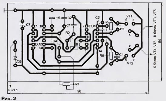
The converter contains a master oscillator on the elements DD1.1, DD1.2, a counting trigger DD2.1, a single vibrator DD2.2, a control pulse shaper on the elements DD1.3, DD1.4 and a push-pull power amplifier on transistors VT1 - VT6. The load is connected through a step-up transformer T1. Each pulse of the master oscillator changes the state of the triggers of the DD2 chip. The signals from the direct and inverse outputs DD2.1 and the direct output DD2.2 are fed to the inputs of the elements DD1.3, DD1.4, and voltage pulses alternately appear at their outputs, opening transistors VT1 and VT2. A single vibrator is assembled on DD2.2, which is switched on at input C and generates a pulse with a duration determined by the R3R4C2 integrating circuit. This limits the duration of the open state of transistors VT1, VT2 and, accordingly, VT3, VT5 and VT4, VT6. As a result, a temporary "gap" is created, excluding the simultaneous presence of transistors in the open state, i.e. through current. By changing this "gap" from 0,4 to 3,2 ms with a variable resistor R3, the output voltage of the converter is regulated within about 40 V. In this case, of course, the shape of the output voltage and the spectrum of interference created by the device change. Through current-limiting resistors R5, R6 and boost capacitors C3, C4, pulses from the outputs of elements DD1.3, DD1.4 arrive at the bases of transistors VT1, VT2, which control the operation of the output transistors connected to them according to the Shiklai circuit. (This combination of npn and pn-p transistors behaves like a single npn transistor with a large base current transfer ratio). Resistors R7, R8 serve to increase the closing speed of transistors. Diodes VD1, VD2 allow you to turn on the converter without load, protect the device if the polarity of the battery connection is not observed and work as a rectifier when charging the GB1 battery. Diode VD3 performs the function of decoupling the supply of microcircuits and can be replaced by a resistor with a resistance of 50 ... 100 ohms. Transformer T1 raises the voltage in converter mode and lowers it in charger mode. Capacitor C8 serves to reduce voltage surges in the charging circuit, C9 smoothes surges when operating in converter mode. LEDs HL1 and HL2 indicate the operating modes of the device. Switch Q1 selects the operating mode of the device, switch Q2 regulates the output voltage within 225 ... 255 V (with a minimum temporary "gap" and idling) in converter mode and charging current up to 6 A (with closed contacts of switch Q3). Microcircuits, transistors VT1, VT2, resistors R1, R2, R4 - R6, capacitors C1 - C7 and a diode VD3 are mounted on a printed circuit board made of foil fiberglass, made according to the drawing in fig. 2 (dashed lines show jumper wires connecting printed conductors on the opposite side of the board). The power part is made by hinged mounting. Transistors VT3 - VT6 and diodes VD1, VD2 are installed on a common heat sink with an area of 600 cm2. There are no special requirements for these elements of the device (in particular, the selection of transistors according to any parameter is not required).
Capacitors C1 and C2 must be with a small TKE (for example, K73-17), the rest - of any type. Ammeter RA1 - with measurement limits of 10A and zero in the middle of the scale (10A - 0 - 10A). Transformer T1 is made on the basis of TS - 180 from a unified TV. All its secondary windings are removed, and the network is used as an output (in converter mode). Sections 2 - 3 and 2' - 3' of the network winding (designations on the transformer) are also removed, and new windings 2 - 5 and 2' - 5' are wound in their place (51 turns of wire PEV-2 0,64), making taps from the 17th and 34th turns (3, 4 and 3', 4'). In place of the secondary windings, two primary ones (9-10 and 9'-10') are wound with 36 turns of PEV-1 1,8 wire. The windings are wound in one direction, after which their ends are connected (this will be the middle point). For better cooling, no external insulation of these windings should be done. It is recommended to turn on the device for the first time without load and with a FU1 2 A fuse. If the parts are in good condition and there are no installation errors, it starts working immediately. The adjustment comes down to setting the frequency of the master oscillator (by selecting the resistor R2) equal to 100 Hz. If the converter will not be used to power devices containing AC motors (players, reel-to-reel tape recorders, etc.), it is recommended to select a higher conversion frequency, for example, 80 Hz (master oscillator frequency - 160 Hz), which will facilitate the operation of transformers power supply for connected devices. It may be necessary to select resistors R5, R6 (the author did not need this) so that the output transistors reliably enter saturation. To increase the efficiency of the device in the output stage of the power amplifier (VT3-VT6), field-effect or germanium bipolar transistors can be used. Author: V.Grichko, Krasnodar
Machine for thinning flowers in gardens
02.05.2024 Advanced Infrared Microscope
02.05.2024 Air trap for insects
01.05.2024
▪ Men are less tolerant of heat ▪ DDR4 chip based on third-generation 10nm class technology
▪ section of the site Cultivated and wild plants. Article selection ▪ article Black mark. Popular expression ▪ article On whose planes in 1916 were red stars identified? Detailed answer ▪ article solar distiller. Travel Tips
Home page | Library | Articles | Website map | Site Reviews
www.diagram.com.ua |


 Leave your comment on this article: