|
|
ENCYCLOPEDIA OF RADIO ELECTRONICS AND ELECTRICAL ENGINEERING UCU power supply, 2x51/2x32 volts. Encyclopedia of radio electronics and electrical engineering
Encyclopedia of radio electronics and electrical engineering / Power Supplies Now many lovers of high-quality sound reproduction independently manufacture AF amplifiers with very high performance and output power up to tens of watts. All links of the amplifying path, and often auxiliary devices, switching elements, indications, etc. are subjected to constant improvement. The desire to achieve maximum UCU quality indicators is increasingly forcing designers to reconsider their positions in relation to power supplies. This is understandable - after all, with a large current consumption, the simplest smoothing filters are no longer able to provide satisfactory stability of the supply voltage, and this significantly affects the sound quality. When the peaks of the signal are reproduced, the voltage fluctuations at the filter output reach 5 V or more, and this makes it necessary to provide a supply voltage reserve for the power amplifier. But the reserve leads to a heavier operating mode of the output transistors of the amplifier and, as a result, to a decrease in its efficiency and reliability. Therefore, an increasing number of radio amateurs prefer stabilized power supplies. In addition, it is easy to introduce an overload protection device into the stabilizer, which is highly desirable, given the cost of powerful transistors and the laboriousness of replacing them. What characteristics should a high-quality power amplifier power supply have? The most important requirements for the UCU power supply include ensuring the necessary output power at given stabilization and ripple suppression coefficients, high reliability and efficiency of the protection system, the maximum possible simplicity of the circuit and design, temperature stability of the protection system and the stabilizer as a whole. It has been noted that a stabilizer designed to work with a power amplifier does not require a too large value of the stabilization coefficient Kst, which usually leads to a significant complication of the circuit. As practice has shown, a high-quality power amplifier works perfectly with a stabilizer having Kst = 30. Fluctuations in the supply voltage during the reproduction of signal peaks (at output power Pout = 60 W) did not exceed 0,2 V and additional distortions, which are common under these conditions when the AF amplifier is powered from an unstabilized source, did not occur. Consider the issues of choosing the supply voltage and the threshold of operation of the protection device. The output voltage Upit (Fig. 1) of one arm of the power supply must be equal to:
where Imax is the current value, A at the maximum output voltage swing; Uke us - saturation voltage of the output transistor, V; Rн - load resistance, Ohm, Ros - resistance of the feedback resistor in the emitter circuit of the output transistor Ohm.
Let's take Rn = 4 ohms, since this is the most typical case for a powerful amplifier. If we substitute numerical values into the indicated inequality, it is easy to make sure that the voltage of one arm of the power supply for an amplifier with a power of 60 ... 80 W lies within 27 ... 33 V. Let us dwell on the issue of determining the threshold for operating the current protection system. It is quite clear that this threshold must be such that undistorted reproduction of the signal at maximum output power is ensured. On the other hand, the threshold should not exceed the Imax value of the output transistors. As you know, the useful power in the load
whence
Based on this ratio, a table of values for the operation threshold Iz of the current protection system for various output power values has been compiled. The table corresponds to the case when each channel of the amplifier is powered by a separate stabilizer (if both power amplifiers are powered by a common source, the response threshold should be doubled). Approximately, Iz = (1,03 ... 1,07) Imax can be taken.
Based on the foregoing - and this is confirmed by practice - we can conclude that it is not advisable to power both power amplifiers from one stabilized source. Another important issue is the choice of the type of protection system. Protective devices with current stabilization in emergency mode cannot be used here. The fact is that, as a rule, when the load circuit is closed, a very large current will flow through the regulating transistor of the stabilizer. If measures are not taken immediately to limit it, a thermal breakdown of the regulating transistor of the stabilizer is possible, and after this often the output transistors of the power amplifier. Protection devices with the closing of the regulating transistor have a relatively low, but quite sufficient speed. There are two types of such devices - with self-return and with a "trigger effect". The former automatically return the stabilizer to operating mode after the cause of the overload has been eliminated. The second ones leave the regulating transistor of the stabilizer closed, and it is possible to return it to the stabilization mode after the accident has been eliminated only by external influence. In our opinion, it is undesirable to use self-resetting devices to protect a power amplifier. If the overload is cyclical (for example, when playing a phonogram with the maximum level), the power to the amplifier will be intermittent due to the periodic operation of the protection system. This will lead to repeated repetition of the transient process in the amplifier, which can cause it to fail. Devices with a "trigger effect" are more preferable. They are very effective in the process of setting up, testing and repairing amplifiers, when the probability of an emergency is quite high. Taking into account all the above considerations, a stabilizer was developed, the scheme of which is shown in Fig. 2.
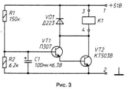
The stabilizer is made according to a compensation scheme using a composite transistor in the control element. Both stabilizer arms are schematically the same. The use of a D818B zener diode in the control element, which has a negative TKN stabilization, made it possible to drastically reduce the temperature drift of the output voltage. The use of transistors of different structures in the comparison device (VT4) and the regulating element (VT1) leads, on the one hand, to the need to introduce stabilizer start-up circuits. On the other hand, this construction also provides some advantages. In particular, only a short switching pulse is needed to trigger the protection system in order to securely close the adjusting element of the stabilizer. This state is very stable and there is no need for the transistor of the VT3 protection system to be constantly open after its operation. The start circuit is a resistor R3, a shunting control element and connected by contacts K1.1 of the time relay (Fig. 3). In the initial state (the power supply is de-energized), contacts K1.1 and K1.2 of relay K1 are closed. After applying power for about 1 s, the stabilizer starts up. The relay then energizes, the contacts open and the start circuit is deactivated.
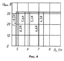
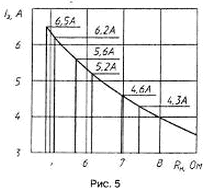
In the event of an overload or short circuit of the load circuit, the voltage drop across the resistor R7 slightly opens the transistor VT3. Because of this, the transistor VT4 begins to close, followed by the transistors VT1 and VT2. A decrease in the voltage at the emitter of the transistor VT3 leads to an even greater opening, and the control element closes like an avalanche (relay K1 remains on). After the protection system has tripped, the output voltage and current through the load circuit are very small. Even when the case of the transistor VT80 is heated to 2 ° C, they do not exceed 2 mV and 100 μA, respectively. To transfer the stabilizer to the operating mode after eliminating the cause of the overload, turn off the power to the amplifier for a short time. On fig. Figures 4 and 5 show experimentally taken graphical dependences of the output voltage and load current on the load resistance at various values of the protection system operation threshold.
For the purpose of complete power decoupling, a separate stabilizer is provided for each amplifier channel. The rectifiers are made according to a full-wave bridge circuit with smoothing capacitive filters. The total current transfer coefficient of the composite transistor VT1 and VT2 must be at least 70000, and the transistor VT4 must be more than 100. In order to improve the clarity of the protection operation, the static current transfer coefficient of the transistor VT3 must be at least 150.
Transistors VT2 and VT6 are each installed on a heat sink with a usable area of 1000 cm2 through insulating gaskets. Thermally conductive grease is applied to the gaskets on both sides. KPT-8 (GOST 19 783-74), which made it possible to significantly reduce the thermal resistance of the transistor case - heat sink. Transistors VT1 and VT5 are mounted on heat sinks made of duralumin corner profile 15x15 mm and having a surface area of about 10 cm2. The stabilizer uses tuning resistors SP4-1. Capacitors C1, C2 - KM-5, the rest - K50-6. Resistors R7, R20 - wire. Instead of the KT814V transistor, you can use KT816V, KT816G, KT626V, KT626D; instead of KT827V - KT827B; instead of KT315G - KT503G, instead of KT503E - KT602B, KT603B, KT503B, KT503G, KT3102A - KT3102V, KT3102D, KT3102E; instead of KT815V - KT817V, KT817G, KT961A, KT807A, KT807B, KT801A, KT801B; instead of KT825V - KT825A, KT825B, KT825G; instead of KT361G - KT501E, KT501K, KT502B, KT502G, KT3107B, KT3107I; instead of KT502E - KT502G, KT502D, KT501M. To establish a stabilizer, you need a voltmeter, an ammeter, a load resistor with a power of 250 ... 300 W (for example, a rheostat. RSP-2); it is also desirable to have an oscilloscope with a closed input and a cutoff frequency of at least 1 MHz. Adjust alternately all the shoulders of the stabilizers. First, the stabilizer is started without load by briefly connecting the resistor R3, setting the desired output voltage with the tuning resistor R12. The rheostat is transferred to the maximum resistance and connected through an ammeter to the output of the stabilizer. If the voltmeter readings have not changed, there is no self-excitation. Otherwise, you will have to pick up the capacitor C1. The protection system is adjusted by first setting the engine of the tuning resistor R8 to the lower position according to the diagram. By reducing the load resistance, they achieve an ammeter reading equal to the threshold, then move the slider of the resistor R8 until the protection trips. The rheostat is returned to the position of maximum resistance, the power supply of the stabilizer is turned off and on again, and the load resistance is again reduced until the protection is triggered. If necessary, the position of the slider of the resistor R8 is corrected. It is necessary to establish a protection system quickly so as not to overheat the powerful transistor of the regulating element. Repeated tests have shown the high reliability of the stabilizer and the effectiveness of the protection system, which confirms the correct approach to designing a power supply for a power amplifier. Authors: E. Mitskevich, I. Karpinovich
Machine for thinning flowers in gardens
02.05.2024 Advanced Infrared Microscope
02.05.2024 Air trap for insects
01.05.2024
▪ The oceans are warming faster than expected ▪ Battery Power System for NB-IoT Wireless LTE Module ▪ Lavo home hydrogen batteries
▪ section of the site Note to the student. Article selection ▪ article Automatic greenhouse. Drawing, description ▪ article A furniture upholsterer co-authored what discovery in medicine? Detailed answer ▪ article Meadow mint. Legends, cultivation, methods of application ▪ article solar charger. Encyclopedia of radio electronics and electrical engineering ▪ article Pulse voltage converters. Encyclopedia of radio electronics and electrical engineering
Home page | Library | Articles | Website map | Site Reviews www.diagram.com.ua |


 Arabic
 Bengali
 Chinese
 English
 French
 German
 Hebrew
 Hindi
Hindi Italian
 Japanese
 Korean
 Malay
Malay Polish
 Portuguese
 Spanish
 Turkish
 Ukrainian
 Vietnamese


 Leave your comment on this article: