|
|
ENCYCLOPEDIA OF RADIO ELECTRONICS AND ELECTRICAL ENGINEERING Power supply for children's electrified toys, 220/12 volts. Encyclopedia of radio electronics and electrical engineering
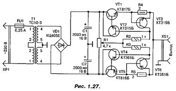
Encyclopedia of radio electronics and electrical engineering / Power Supplies Most children's electrified toys are powered by galvanic cells and batteries. Therefore, there often comes a moment when the energy of the power source dries up, but there is no new one. The toy ceases to function at all, and the children begin to get on your nerves with requests for batteries. This will not happen if you make the proposed power source and connect one or another toy to it. It is especially suitable for moving toys, for example, for the railway. Then the speed and direction of movement of the steam locomotive with wagons can be smoothly changed by the source control knob. The source (Fig. 1.27) consists of a rectifier and two identical electronic voltage regulators with protection against overload and short circuit in the load. The rectifier is assembled on a VD1 diode bridge in a full-wave circuit with a midpoint. The diode block is connected to the secondary winding of the power transformer T1, consisting of two identical windings connected in series, forming a common winding with an average output - this is the middle point of the rectifier. The rectified voltage is filtered by capacitors C1, C2 connected in series and connected to the midpoint. As a result, at the output of the rectifier, a bipolar constant voltage is obtained, which is 12 V relative to the midpoint.
At the output of the capacitor C2 - minus 12 V. Electronic regulators are connected to these sources, controlled by the voltage taken from the variable resistor R1 engine. Each regulator is composed of two transistors (VT1, VT2 and VT4, VT5) forming a composite emitter follower. In the middle position of the resistor slider, the voltage across it will be close to zero relative to the common wire. Therefore, the transistors of the regulators are closed, there is no voltage at the sockets of the XS1 connector. When the variable resistor slider is moved down the circuit, transistors VT1, VT2 remain closed, and VT4, VT5 open. A negative voltage appears at the output of the power supply (connector XS1) (on the upper conductor of the connector in relation to the lower one). Moreover, the closer to the lower output of the variable resistor is the engine, the greater the output voltage. If you start moving the variable resistor slider from the middle position to the top output according to the circuit, the opposite picture will occur, the transistors VT1, VT2 will open, and a positive voltage will appear at the source output. Overload or short circuit protection nodes are made on transistors VT3 and VT6. While flowing, for example, through the resistor R4, the current is within certain limits (in our case, up to 350 mA), the transistor VT3 is closed. As soon as the load current exceeds the set value, the voltage drop across the resistor R4 will increase and the transistor VT3 will open. The emitter junction of the composite transistor (the section between the base of the transistor VT2 and the emitter of the transistor VT1) will be shunted, and the transistor will almost close. The output current of our source will be sharply limited. As soon as the overload or short circuit disappears, the normal operation of the device will be restored. Instead of transistors KT816, KT817, KT814, KT815 are suitable, respectively. The KTs405E diode block can be replaced with KTs402E or four diodes of the KD208, KD209 series.
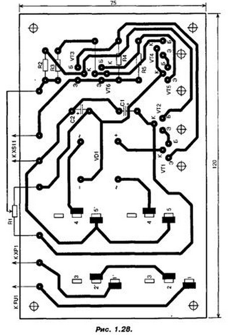
The power transformer can be, in addition to that indicated on the diagram, TP20-14 or any other, with a power of at least 10 W and with a voltage on the secondary windings of 8 ... 12 V at a load current of up to 0,7 A. Transistors are installed on radiators with a total surface area about 35 cm2, which are screwed to the board. The protection trip current depends on the resistances of the resistors R4, R5. It can be increased from 350 to 500 ... 600 mA by reducing the resistance of these resistors to 1,2 ... 1 Ohm, and also by increasing the area of the radiators of transistors VT1, VT5 to 50 ... 60 cm2. The printed circuit board of this device is shown in Fig. 1.28. Author: V.Andrushkevich
Machine for thinning flowers in gardens
02.05.2024 Advanced Infrared Microscope
02.05.2024 Air trap for insects
01.05.2024
▪ Electronics will help the driver of the car to avoid an accident ▪ Bee moth against polyethylene
▪ section of the site Riddles for adults and children. Article selection ▪ article Yes, only things are still there. Popular expression ▪ article Who Invented the Helicopter? Detailed answer ▪ article The functional composition of Pedcock TVs. Directory ▪ article Adaptation of imported phones. Encyclopedia of radio electronics and electrical engineering ▪ article S-meter calibrator. Encyclopedia of radio electronics and electrical engineering
Home page | Library | Articles | Website map | Site Reviews www.diagram.com.ua |


 Arabic
 Bengali
 Chinese
 English
 French
 German
 Hebrew
 Hindi
Hindi Italian
 Japanese
 Korean
 Malay
Malay Polish
 Portuguese
 Spanish
 Turkish
 Ukrainian
 Vietnamese


 Leave your comment on this article: