|
|
ENCYCLOPEDIA OF RADIO ELECTRONICS AND ELECTRICAL ENGINEERING Interference-resistant acoustic switch. Encyclopedia of radio electronics and electrical engineering
Encyclopedia of radio electronics and electrical engineering / Lighting An acoustic switch for an incandescent lamp is described. The electrical circuit diagram and the layout of the printed circuit board of the device are given. In the author's version, a ZP-3 piezo emitter was used as a microphone. The circuit does not contain scarce details, special attention in the development of the acoustic switch is paid to resistance to interference in the power supply. The idea of an acoustic switch is not new, so the author, setting out to make such a device for himself, tried to find a ready-made solution in order to repeat the design without any hassle. However, after getting acquainted with the found materials [1-4], I had to look for my own circuit solution. The owner of a cafe in a European city equipped his establishment with unusually bulky furniture. Adult visitors, entering the cafe, see tables and chairs the same as 4-5-year-old children. This is done so that parents feel the inconvenience and think about children's problems. Toddlers really have a hard time because of their small stature. For example, they cannot turn on the light in the toilet themselves, each time they have to turn to adults. An acoustic switch can help them. I had another reason for installing such a switch. In the corridor of the apartment, the builders once installed a 4-position switch with a cord that worked on one light bulb, which eventually broke down. Currently, I do not see such single or multi-position switches for sale. As an acoustic switch microphone, I decided to use a piezoelectric emitter. The circuit of the original version of the acoustic switch (Fig. 1) contains a ZP-3 type piezoelectric sensor, an AC voltage amplifier (ACV) on a DA1 chip, a waiting multivibrator on a DD1.1 chip, a DD1.2 trigger, a power amplifier on a VT3 transistor. The power supply of the circuit is transformerless. The mains voltage is rectified by the VD1 diode assembly and fed to the parametric stabilizer on the VD2 zener diode. The pulsating voltage from the zener diode is supplied to an analogue of a two-base diode assembled on transistors VT1 and VT2, and also through a diode VD3 to capacitor C5, which serves as a filter. An analog of a two-base diode includes a thyristor VS1, provided that the capacitor C5 is not shunted by the transistor VT3, and this depends on the state of the trigger. VS1 is loaded with a 15-100W incandescent lamp. The UPN is built according to one of the typical schemes for switching on an operational amplifier from a single power source [5]. The amplifier contains a small number of parts and allows you to simply adjust the sensitivity of the switch by changing the value of the resistor R4. With an increase in the resistance of the resistor R4, the sensitivity increases and, accordingly, with a decrease in the resistance R2 decreases. As a result of cotton at the output of the OPN, a burst of pulses is obtained. The waiting multivibrator is triggered by one of these pulses and generates its own pulse, the duration of which exceeds the duration of the clap. Therefore, the DD1.2 trigger switches with each clap, and not with individual pulses of the pack. The scheme immediately worked perfectly. Clap your hands - the lamp turns on, the second clap - the lamp turns off. It would be possible to stop at this, if not for one "but" the lamp turns on not only under duress, but also from accidental interference in the power supply. In addition, the device has another disadvantage - when voltage is applied to the device, the lamp, as a rule, lights up. This is undesirable, because in the event of a power failure and the subsequent supply of electricity, the lamp must be forcibly turned off. If there is no one at home - an extra consumption of electricity. But this shortcoming is quite easy to eliminate - it is enough to force the D1.2 trigger on input S when the device is turned on. With random interference in the network, you can fight for a long time and, possibly, to no avail. The circuit of the device is designed so that it does not need to be configured. It can be recommended as a basis for the development of a similar battery- or battery-powered device. After analyzing the circuits of devices described in the literature [1-4], I decided to borrow a trigger analog circuit with a counting input on an electromagnetic relay [2]. Old fashioned? But it's safe and easy. After all, to turn on the relay, it is necessary to expend much more energy than to switch a high-speed trigger with a high-resistance input.
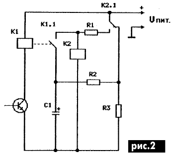
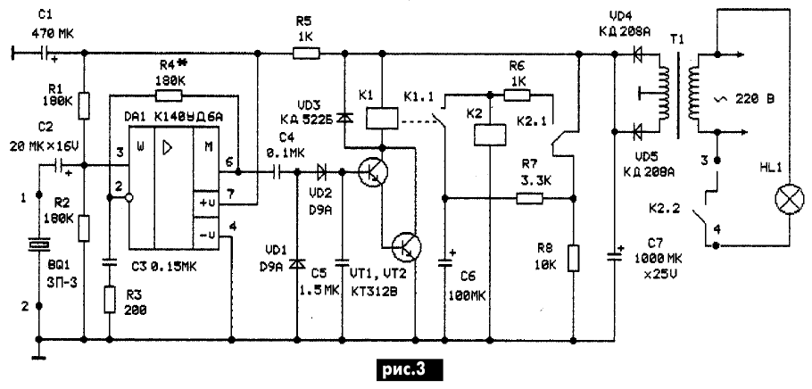
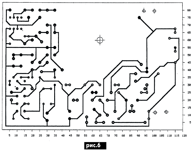
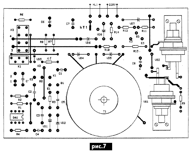
The relay trigger circuit (Fig. 2) works as follows. In the initial state, the capacitor C1 is charged through the contacts of the relay K2.1, and the resistor R2 is charged to the supply voltage, the winding of the relay K2 is de-energized. Under the influence of an acoustic signal, the contacts of relay K1.1 are briefly closed. The energy of the capacitor turns on relay K2, its contacts switch to self-hold. After exposure to an acoustic signal, the contacts of the contact group K1.1 open, and the capacitor C1 is discharged through resistors R2 and R3. With the subsequent arrival of an acoustic signal, the contacts of group K1.1 are briefly closed. Capacitor C1 is charged through resistor R1, shunting the winding of relay K2, as a result of which it is de-energized, and relay K2 turns off. The waiting multivibrator is started (Fig. 1) through the differentiating chain C3R7. Differentiating chains are not noise-immune, unlike integrating ones. The decision suggests itself. As a result of the experiments, the final version of the device appeared (Fig. 3). The device contains all the same OPN, a classic diode amplitude detector (VD1, VD2 and C5), a DC amplifier on a composite transistor (VT1 and VT2) and a trigger on electromagnetic relays described in detail above. In the noise-immune circuit of the acoustic switch, pulses from the output of the OPV are detected by an amplitude detector. During the clap, a constant voltage appears on the capacitor C5, supplied to the base of the composite transistor loaded on the winding of the relay K1. When using the radio elements indicated in the diagram, the acoustic switch does not need to be adjusted and has good repeatability. Relay K1 type RES49 has the following passport data: winding resistance Rb 1900 Ohm, operation current I no more than 8 mA, i.e. according to the passport for this relay, the response voltage is U = RobI = 15,2 V. The passport data of the relay K2 type RES47 are as follows: winding resistance 650 Ohm, response current not more than 21,5 mA. Similarly, according to the passport data for RES47, the operation voltage is 14 V. When replacing the relay, it should be checked that the device supply voltage is several volts higher than the operation voltage of the applied relays. To power the circuit, a power transformer with an output voltage of 2x15 V was used. The rectified DC voltage is approximately 17 V. The DC current consumption of the device does not exceed 30 mA. With a large spread of relay parameters from those applied, in case of their replacement, it may be necessary to change the nominal values of the remaining trigger elements. The acoustic switch can also work with other sources of sound signals. The operation of the device with a dynamic microphone MD-201 was tested. Due to the fact that the UPN was energized, possibly due to the microphone cord, a 0,1uF capacitor had to be added in parallel with the microphone input for this case. This capacitor is not shown in the diagram, but a place is left for it in the design of the printed circuit board, designated C`. An acoustic switch can be equipped with a device for two-stage switching on of an incandescent lamp in order to increase its durability [6]. One version of such a device is shown in Fig. 4, and the second - in Fig. 5. The printed circuit board of the acoustic switch with dimensions of 85x120 mm is shown in Fig. 6, the location of the elements on the printed circuit board is shown in Fig. 7.
The printed circuit board is designed taking into account the connection of a device for two-stage switching on of an incandescent lamp according to the scheme of fig. 5. Single-sided printed wiring using insulated wire jumpers. In a device without changing the pattern of the printed circuit board, instead of the K140UD6A microcircuit, you can use K140UD7, K140UD8, K544UD1, K544UD2. Ceramic capacitors C2C5 type KM3, KM4, KM5, KM6 or K10-17, K10-47. Electrolytic capacitors C1, C6-C8 type K50-16, K50-35. Transformer T1 - any low-power secondary voltage of 15-20 V. If the transformer has one winding, then a diode bridge should be used for the rectifier. After assembling the board, you need to make sure that the parts are installed correctly, then proceed to check the device's performance. Attention! The printed circuit board has a life-threatening voltage of 220 VAC, so extra care and the following recommendations must be observed. First, check the operation of the acoustic switch without a two-stage incandescent lamp switching device. Using an ohmmeter, measure the load resistance of the rectifier for a short circuit. Then, without connecting them to the board, supply 220 V to the network terminals of the power transformer, after insulating the connection points with electrical tape or a PVC tube. Check the operation of relay K2 from claps in the palm of your hand at a sufficient distance from the sound sensor. If everything is in order, then apply a voltage of 220 V to the board, connect an incandescent lamp and check it in the complex. At the last stage, solder the mains leads of the transformer to the board and mount it and the sound sensor in a suitable case. After this operation, if necessary, you can set the required sensitivity of the device by selecting the resistor R4. When using the device, it must be taken into account that it is not suitable for noisy places, for example, a blacksmith shop. You should not install it near a loud phone call. The operation of the acoustic switch for about six months showed that it only works from sound signals. References:
Author: V. Samelyuk
Air trap for insects
01.05.2024 The threat of space debris to the Earth's magnetic field
01.05.2024 Solidification of bulk substances
30.04.2024
▪ Portable Pet Hair Vacuum Cleaner ▪ The ozone layer is recovering ▪ Traces of a collision of two super-Earths discovered ▪ Found an important difference between the human brain and other primates
▪ site section Chargers, accumulators, batteries. Article selection ▪ article Popular about the device of the lens. video art ▪ article Who Invented the Airplane? Detailed answer ▪ article Camp kitchen. Tourist tips ▪ article Waterproofing and fire resistance of materials. Simple recipes and tips ▪ Article Amazing power. Focus Secret
Home page | Library | Articles | Website map | Site Reviews www.diagram.com.ua |


 Arabic
 Bengali
 Chinese
 English
 French
 German
 Hebrew
 Hindi
Hindi Italian
 Japanese
 Korean
 Malay
Malay Polish
 Portuguese
 Spanish
 Turkish
 Ukrainian
 Vietnamese


 Leave your comment on this article: