|
|


 Arabic
 Bengali
 Chinese
 English
 French
 German
 Hebrew
 Hindi
Hindi Italian
 Japanese
 Korean
 Malay
Malay Polish
 Portuguese
 Spanish
 Turkish
 Ukrainian
 Vietnamese
|
ENCYCLOPEDIA OF RADIO ELECTRONICS AND ELECTRICAL ENGINEERING Stabilized adjustable power supply 220/0-30 volts 7,5 amps with overload protection. Encyclopedia of radio electronics and electrical engineering
Encyclopedia of radio electronics and electrical engineering / Regulators of current, voltage, power A lot of amateur radio power supplies (PSUs) are made on KR142EN12, KR142EN22A, KR142EN24 chips, etc. The lower adjustment limit of these microcircuits is 1,2 ... 1,3 V, but sometimes a voltage of 0,5 ... 1 V is necessary. The author offers several technical solutions for a PSU based on these microcircuits. The integrated circuit (IC) KR142EN12A (Fig. 1) is an adjustable voltage regulator of the compensation type in the KT-28-2 package, which allows you to power devices with a current of up to 1,5 A in the voltage range of 1,2 ... 37 V. This integrated The stabilizer has thermally stable current protection and output short circuit protection.
Based on the IC KR142EN12A, it is possible to build an adjustable power supply, the circuit of which (without a transformer and a diode bridge) is shown in fig. 2. The rectified input voltage is supplied from the diode bridge to the capacitor C1. Transistor VT2 and chip DA1 must be located on the radiator. The heat sink flange DA1 is electrically connected to pin 2, so if DA1 and the transistor VD2 are located on the same heatsink, they must be isolated from each other. In the author's version, DA1 is installed on a separate small heatsink, which is not galvanically connected to the heatsink and transistor VT2.
The power dissipated by a chip with a heat sink must not exceed 10 watts. Resistors R3 and R5 form a voltage divider included in the measuring element of the stabilizer, and are selected according to the formula: UO = Uout.min ( 1 + R3/R5 ). A stabilized negative voltage of -2 V is supplied to the capacitor C2 and resistor R1 (used to select the thermally stable point VD5). To protect against a short circuit of the output circuit of the stabilizer, it is enough to connect an electrolytic capacitor with a capacity of at least 3 μF in parallel with the resistor R10, and shunt the resistor R5 with a KD521A diode. The location of the parts is not critical, but for good temperature stability it is necessary to use the appropriate types of resistors. They should be located as far as possible from heat sources. The overall stability of the output voltage is made up of many factors and usually does not exceed 0,25% after warming up. After turning on and warming up the device, the minimum output voltage of 0 V is set by the resistor Radd. Resistors R2 (Fig. 2) and resistor Radd (Fig. 3) must be multi-turn trimmers from the SP5 series.
The current capabilities of the KR142EN12A microcircuit are limited to 1,5 A. Currently, microcircuits with similar parameters are on sale, but designed for a higher current in the load, for example, LM350 - for a current of 3 A, LM338 - for a current of 5 A. Data on these microcircuits can be found on the National Semiconductor website [1]. Recently, imported microcircuits from the LOW DROP series (SD, DV, LT1083/1084/1085) have appeared on sale. These microcircuits can operate at a reduced voltage between input and output (up to 1...1,3 V) and provide a stabilized voltage at the output in the range of 1,25...30 V at a load current of 7,5/5/3 A respectively. The closest domestic analogue of the KR142EN22 type in terms of parameters has a maximum stabilization current of 7,5 A. At the maximum output current, the stabilization mode is guaranteed by the manufacturer at an input-output voltage of at least 1,5 V. The microcircuits also have built-in protection against exceeding the current in the load of an acceptable value and thermal protection against overheating of the case. These stabilizers provide output voltage instability of 0,05%/V, output voltage instability when the output current changes from 10 mA to the maximum value no worse than 0,1%/V. On fig. 4 shows a power supply circuit for a home laboratory, which allows you to do without transistors VT1 and VT2, shown in fig. 2. Instead of the DA1 KR142EN12A chip, the KR142EN22A chip was used. This is an adjustable regulator with a low voltage drop, allowing you to get a current of up to 7,5 A in the load.
The maximum power dissipation at the output of the stabilizer Pmax can be calculated by the formula: РMax = (Uvh - ORO) I.O,
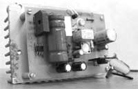
For example, the input voltage applied to the chip, Uvh=39 V, output voltage at the load UO=30 V, load current IO\u5d 45 A, then the maximum power dissipated by the microcircuit at the load is XNUMX watts. The electrolytic capacitor C7 is used to reduce the output impedance at high frequencies, and also lowers the noise voltage level and improves ripple smoothing. If this capacitor is tantalum, then its nominal capacitance must be at least 22 microfarads, if aluminum - at least 150 microfarads. If necessary, the capacitance of the capacitor C7 can be increased. If the electrolytic capacitor C7 is located at a distance of more than 155 mm and is connected to the PSU with a wire with a cross section of less than 1 mm, then an additional electrolytic capacitor with a capacity of at least 7 microfarads is installed on the board parallel to the capacitor C10, closer to the microcircuit itself. The capacitance of the filter capacitor C1 can be determined approximately, based on 2000 microfarads per 1 A of output current (at a voltage of at least 50 V). To reduce the temperature drift of the output voltage, the resistor R8 must be either wire or metal-foil with an error of no worse than 1%. Resistor R7 is the same type as R8. If the KS113A zener diode is not available, you can use the assembly shown in fig. 3. The protection circuit solution given in [2] suits the author quite well, since it works flawlessly and has been tested in practice. You can use any BP protection circuit solutions, for example, those proposed in [3]. In the author's version, when relay K1 is activated, contacts K1.1 close, shorting resistor R7, and the voltage at the PSU output becomes 0 V. The printed circuit board of the PSU and the location of the elements are shown in fig. 5, the appearance of the PSU - in fig. 6. PCB dimensions 112x75mm. Radiator selected needle. The DA3 chip is isolated from the heatsink by a gasket and attached to it with a steel spring plate that presses the chip to the heatsink.
Capacitor C1 of type K50-24 is composed of two capacitors connected in parallel with a capacity of 4700 μFx50 V. An imported analog of a capacitor of type K50-6 with a capacity of 10000 μFx50 V can be used. The capacitor should be located as close as possible to the board, and the conductors connecting it to the board should be as short as possible. Capacitor C7 manufactured by Weston with a capacity of 1000 uFx50 V. Capacitor C8 is not shown in the diagram, but there are holes on the printed circuit board for it. You can use a capacitor with a rating of 0,01 ... 0,1 μF for a voltage of at least 10 ... 15 V.
Diodes VD1-VD4 are an imported diode microassembly RS602, designed for a maximum current of 6 A (Fig. 4). The RES10 relay (passport RS4524302) is used in the power supply protection circuit. In the author's version, a resistor R7 of the SPP-ZA type was used with a parameter spread of no more than 5%. Resistor R8 (Fig. 4) should have a spread of no more than 1% from the given value. The power supply usually does not require configuration and starts working immediately after assembly. After heating the unit with resistor R6 (Fig. 4) or resistor Rdop (Fig. 3), 0 V is set at the nominal value of R7. In this design, a power transformer of the OSM-0,1UZ brand with a power of 100 W is used. Magnetic core ShL25/40-25. The primary winding contains 734 turns of PEV wire 0,6 mm, winding II - 90 turns of PEV wire 1,6 mm, winding III - 46 turns of PEV wire 0,4 mm with a tap from the middle. The RS602 diode assembly can be replaced with diodes rated for a current of at least 10 A, for example, KD203A, V, D or KD210 A-G (if you do not place the diodes separately, you will have to redo the printed circuit board). As a transistor VT1, you can use the transistor KT361G. Literature
Author: A.N. Patrin, Kirsanov; Publication: cxem.net
Artificial leather for touch emulation
15.04.2024 Petgugu Global cat litter
15.04.2024 The attractiveness of caring men
14.04.2024
▪ Solar panels with human hair ▪ Acer to release 27-inch IPS panel monitor ▪ A new solution for charging and backing up smartphone data
▪ site section Tone and volume controls. Article selection ▪ article Tear like Sidorov's goat. Popular expression ▪ article Rendering first aid in case of poisoning. Health care ▪ article Lollipops. Simple recipes and tips ▪ article Glycerin turns into sugar. Chemical experience
Home page | Library | Articles | Website map | Site Reviews
www.diagram.com.ua |


 Leave your comment on this article: