|
|


 Arabic
 Bengali
 Chinese
 English
 French
 German
 Hebrew
 Hindi
Hindi Italian
 Japanese
 Korean
 Malay
Malay Polish
 Portuguese
 Spanish
 Turkish
 Ukrainian
 Vietnamese
|
ENCYCLOPEDIA OF RADIO ELECTRONICS AND ELECTRICAL ENGINEERING Adjustable power supply 3,3-9 volts 0,5 amps with a switching voltage regulator. Encyclopedia of radio electronics and electrical engineering
Encyclopedia of radio electronics and electrical engineering / Power Supplies The article talks about a low-power power supply with a switching voltage regulator based on a specialized MC34063 microcircuit. In comparison with linear stabilizers, pulse stabilizers have higher efficiency, smaller weight and overall dimensions, but at the same time they have some disadvantages, one of the main ones is an increased level of output voltage ripple. The proposed power supply can be used to power various household devices, multifunctional telephones, game consoles, players, home calls, etc., where the use of a switching regulator will make the AC power supply not only more economical, but also greatly facilitate its temperature regime. It provides an output voltage of 3,3 ... 9 V at a current of up to 0,5 A. The amplitude of the output voltage ripple does not exceed 30 mV at the maximum load current. The switching regulator of the power supply has protection against overcurrent and against the appearance of overvoltage at the output. This stabilizer can be used both in the design of new power supplies, and to replace linear stabilizers in previously manufactured ones, for example, using TVK-110LM, TVK-110L2 transformers popular in the past from tube-semiconductor TVs. In newly manufactured power supplies, the use of a switching voltage regulator will allow the use of a step-down transformer with less power and overall dimensions. The power supply circuit is shown in pic.1.
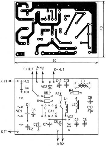
The mains voltage through the fuse-link FU2 and the push-button switch SB1 is supplied to the primary winding of the step-down transformer T1. The AC voltage removed from its secondary winding is fed through a self-healing fuse FU1 to a bridge diode rectifier VD1. The ripple of the rectified voltage is smoothed out by the capacitor C3. Capacitors C1, C2, C4-C6 suppress impulse noise coming from the network and prevent such interference from entering the network from the switching regulator. It is made on a specialized integrated circuit MS34063AP, which is included according to the standard scheme of a step-down stabilized voltage converter. This microcircuit is operable at an input voltage of up to 40 V and a maximum current of the output transistor up to 1,5 A. In this case, its own current consumption is 4 ... 8 mA. The microcircuit contains a protection unit against overload and short circuit in the load circuit. Resistor R1 acts as a current sensor for this node. The conversion frequency is set by the capacitor C7. The output voltage depends on the ratio of the resistances of the resistors R4 and series-connected resistors R2, R3, and it can be changed within 3,3...9 by a variable resistor R2. Choke L1 - cumulative, two-section low-pass filter on chokes L2, L3 and capacitors C8-C13 smooth out the output voltage ripple. LED HL1 indicates its presence. The Zener diode VD3 (stabilization voltage 11 V) protects the load from damage by high voltage in the event of a stabilizer malfunction. When the output voltage exceeds 11 V, the current through the zener diode increases sharply and the self-resetting fuse FU1 jumps into a high resistance state and limits the flowing current. All parts, except for the T1 transformer, the fuse holder FU2 and the SB1 switch, are placed on a printed circuit board made of one-sided foil fiberglass, the drawing of which is shown in pic.2.
If you are upgrading a ready-made power supply, then an already used network step-down transformer may be suitable, it is only necessary that it provides a voltage on the secondary winding of 12 ... 20 V and an output power of 8 ... 10 W. Fixed resistors - C1-14, C2-23, C1-4, MLT, MON, variable - SPZ-9, SP4-1, PPB-1A are suitable. It is undesirable to use variable resistors of the SP-1 series due to low reliability. Oxide capacitors - K50-35 or imported analogues, the rest - ceramic K10-17, KM-5. Resettable fuse FU1 - MF-R050, LP60-050. The D3SBA10 diode bridge can be replaced with any of the KTs422, DB101 - DB107, RB151-RB157 or four diodes, for example, 1N4001-1N4007. We replace the 1N5819 diode with diodes 1N5817, 1N5818, four such diodes can replace the diode bridge, while the efficiency of the power supply will increase. Instead of the zener diode 1N5348, protective diodes 1,5KE10, 1,5KE11 are suitable. The LED can be of any glow color (non-blinking) of the KIPD21, KIPD40, L-53 series. All chokes are wound with wire PEV-2 0,56, L1, L2 each contain 40 turns of wire on a magnetic core of size K17,5x8,2x5 mm made of ferrite 2000NM. Before winding, the magnetic circuits are wrapped with varnished cloth or in three layers with adhesive tape (adhesive tape). The inductor L3 contains 6 turns of double-folded wire wound on a magnetic core with a diameter of 10 mm and a length of 11 mm from 600NN or 400NN ferrite (from a portable radio magnetic antenna). If the DA1 chip heats up significantly, then to facilitate its thermal operation and, therefore, increase the reliability of the device as a whole, it is advisable to glue a small heat sink from a copper or brass plate with dimensions of 60x4,5x0,5 mm. It is bent with the letter "P" and glued to the bottom of the microcircuit housing with AlSil-5 or Radial glue. The surfaces to be glued are preliminarily prepared in accordance with the instructions for the use of the adhesive. With an input voltage of the converter of 12 V, an output voltage of 5 and an output current of 0,5 A, the current consumed from the rectifier does not exceed 0,27 A. This confirms that the efficiency of the switching regulator is higher than that on the KR142EN5A microcircuit. If a power supply with a fixed output voltage is required, the variable resistor on the board is replaced with a wire jumper, and the required resistance of the resistor R3 is found from the expression Uout = 1,25(1+R4/R3). In this case, the zener diode (or protective diode) should be installed with a stabilization voltage of 1 ... 2 V more than the output voltage. Author: A. Butov, p. Kurba, Yaroslavl region; Publication: cxem.net
Machine for thinning flowers in gardens
02.05.2024 Advanced Infrared Microscope
02.05.2024 Air trap for insects
01.05.2024
▪ Cooling electronics with jumping droplets ▪ Computer mouse will evaluate health ▪ Ion-optical quantum microscope sees individual atoms ▪ Miniature sensor with radar technology
▪ site section Tone and volume controls. Article selection ▪ article State policy of environmental protection. Basics of safe life ▪ article What is the Decameron? Detailed answer ▪ article Cayuput tree. Legends, cultivation, methods of application
Home page | Library | Articles | Website map | Site Reviews
www.diagram.com.ua |


 Leave your comment on this article: