|
|


 Arabic
 Bengali
 Chinese
 English
 French
 German
 Hebrew
 Hindi
Hindi Italian
 Japanese
 Korean
 Malay
Malay Polish
 Portuguese
 Spanish
 Turkish
 Ukrainian
 Vietnamese
|
ENCYCLOPEDIA OF RADIO ELECTRONICS AND ELECTRICAL ENGINEERING Phone message auto-recording adapter. Encyclopedia of radio electronics and electrical engineering
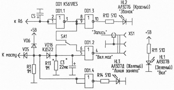
Encyclopedia of radio electronics and electrical engineering / Telephony Replacing a failed Z80 microprocessor-based phone with automatic caller identification (CLI) for a modern one, I noticed that all CLIs manufactured using Intel technology do not contain a tape recorder control port. Unlike older models, they are designed to use only a digital answering machine, the cost of which is almost equal to the cost of the entire device with caller ID. Not wanting to give up using the tape recorder as an answering machine, I decided to assemble one of the devices for automatically turning on the tape recorder when the caller automatically picks up the phone [1-3]. However, these devices have one significant drawback. They work when you pick up the handset, connecting the tape recorder to record both incoming and outgoing calls. This requires the obligatory disconnection of the tape recorder if necessary to call somewhere. I propose a simple device for automatically connecting a tape recorder to the network to record incoming messages. The device is designed to work on the same line with ANI, which issues a standard phrase to the subscriber in the answering machine mode, for example: "An answering machine is working. Speak after the tone ...". At the same time, the device is completely autonomous and does not require intervention in the telephone set. Diagram of the adapter for auto-recording of incoming telephone messages is shown in Fig.1. The voltage from the telephone line (with the handset down - 60 V) through the resistors R1, R2 and the diode bridge (VD1 ... VD4) is reduced by the zener diode VD5 to the supply voltage and charges the capacitor C3. At the same time, at pins 1 and 2 of the element DD1.1 - logical "0", and at output 3 - logical "1". Thus, pins 5 and 6 of DD1.2 are also "1", and at output 4 - "0", which is fed through the buffer elements DD1.3 and DD1.4 to the control contact of the XS1 connector.
A call with a voltage of 4 ... 60 V coming from the telephone line through the resistor R90 is rectified by a rectifier with a doubling of the voltage on the diodes VD7, VD8 and capacitor C4. The ringing voltage is lowered by the Zener diode VD9 to the supply voltage and charges the capacitor C5. At the output 3 of the element DD1.1, a low logic level is formed, which is fed through the switch SA1 to the input 6 of the element DD1.2. This opens the transistor VT1, and the call indication LED HL2 lights up. After the caller ID "picks up" the phone, the voltage in the line drops to 9 ... 12 V, and the VD5 zener diode closes. The discharge of the capacitor C3 through the resistor R3 begins. When a low level is reached at pin 5 of DD1.2, a logical "4" appears at output 1, which switches the elements DD1.3, DD1.4 and supplies a high level control voltage through the XS1 connector to the tape recorder switching unit. Capacitor C3 and resistor R3 provide a turn-on delay for the tape recorder, which is necessary to eliminate false positives when dialing a number and recording a phrase given to a subscriber by AON on a tape recorder. The signal to the line input of the tape recorder is fed through the capacitor C2 and an adjustable resistive divider R7-R8. Diodes VD12, VD13 protect the line input of the tape recorder, lowering the ringing voltage to a safe level. As soon as the subscriber on the other end of the wire hangs up, short "busy" signals will force the caller ID to remove the line hold, and the voltage in it will return to its original level (60 V), ensuring that a high level element DD5 appears at input 1.2 and switches to the initial state. If for some reason the subscriber or caller does not hang up within a few minutes, the duration of the recording will be limited by the discharge time of the capacitor C5 through the resistor R6. The VD10 diode serves to eliminate the shunting effect of the load resistor R5 when the capacitor C5 is discharged through the resistor R6. Diodes VD11 and VD6 stabilize the level of the charging voltage on the capacitors C3 and C5, thus ensuring the constancy of the time intervals for the operation of the device. The SA1 switch can disable the outgoing call recording blocking node if it becomes necessary to record all conversations. The HL2 LED will still indicate incoming calls. To successfully work with the proposed device, the tape recorder must be modified. The author used a tape recorder-prefix "Radio engineering MP-7301". A control unit assembled according to the standard scheme [4] was mounted in the tape recorder. The high-level voltage coming through the XS1 connector through the VU1 thyristor optocoupler opens the VS1 thyristor, which closes the diagonals of the VD15 diode bridge connected in parallel to the tape recorder's mains switch. The contact of the mains switch of the tape recorder must be closed by jumper E1. A tape recorder pre-set for recording (a cassette is installed, the recording level is adjusted, the "Playback" and "Record" keys are pressed) is turned on by a call signal and starts recording information coming from the telephone network. If the tape recorder is equipped with an auto-stop, then it must be blocked in recording mode, since if you disconnect from the network after recording the first message, the auto-stop will disable the record and playback keys, and the next message will no longer be recorded. To do this, an additional button is installed in the tape recorder (for example, from the KM1 microswitch), which, when the "Record" button is pressed, turns off the winding of the hitchhiking electromagnet. In all other modes, hitchhiking should work normally. The adapter uses the widely used K561LE5 chip. Almost all microcircuits of this series work well at a reduced supply voltage. The supply voltage of 5 V is selected for the operation of the device from the AON power supply or from a low-power power supply, for example, for a calculator. A similar microcircuit of the K176 series can be used in the circuit, however, the supply voltage must be increased to 9 V, which will lead to a change in the values of the elements of the timing circuits, resistors R10 and R11, zener diodes VD5 and VD9. As rectifier bridge diodes VD1 ... VD4, any rectifier diodes with a permissible reverse voltage of at least 100 V or diode assemblies can be used. The author used a KD906A diode microassembly. Diodes VD6, VD10...VD14 can be replaced by any silicon. Transistor VT1 can also be replaced by any appropriate conductivity, for example, KT209, KT321, KT326, KT343, KT3107, etc. Thyristor VS1 is suitable for KU201K, KU202K ... N. The rectifier diode assembly VD15 is replaced by KTs402A...G, KTs405A...G or assembled on diodes KD226V...D, KD258B...D. The operating voltage of separating capacitors C1, C2, C4 must be at least 100 V. As the XS1 connector, the author used a miniature connector for connecting stereo telephones, connected by a shielded stereo cord to the line-in jack of the tape recorder. One of the contacts of the line input (without disconnection from the circuit, because the input of the tape recorder has an isolation capacitor) is used to supply control voltage to the turn-on unit of the tape recorder. The adapter is assembled on a board, the dimensions of which depend on the type of radio elements used, and can be placed in any suitable housing or directly in the telephone housing. The values of the values of the elements of the timing circuits depend to a large extent on the parameters of the telephone line. First you need to make sure that the turn-on unit of the tape recorder is working properly by applying a positive voltage of 14 ... 3 V to the VD5 diode. Then the adapter is connected to the tape recorder and to the telephone network, and the SA1 switch is set to the lower position according to the diagram. The voltage across capacitor C3 should be approximately equal to the supply voltage. Picking up the handset on the telephone set should lead to a gradual discharge of the capacitor C3 and turn on the tape recorder. Returning the tube to the lever should cause the tape recorder to turn off at the same time. If the tape recorder does not turn on when the tube is lifted, then the VD5 zener diode is replaced with a zener diode with a high stabilization voltage or another zener diode is added in series. If the tape recorder is always on or turns on and does not turn off when the handset is dropped, then the stabilization voltage value VD5 is too high, or the resistance of the resistor R3 is too high and does not provide the minimum stabilization current. In this case, the value of R3 should be reduced to 500...620 kOhm. The turn-on delay time of the tape recorder is determined by selecting the value of the capacitance of the capacitor C3 so that the recording starts immediately after the caller "pronounces" the phrase "... Speak after the signal." It is better to configure the node for selecting incoming calls and the duration of the recording after measuring the parameters of the ringing signal using a simulator in the form of a step-down network transformer with an output voltage of 60 ... 90 V. This voltage is applied briefly to the input of the device. Measure the voltage drop across the zener diode VD9, which should be equal to its stabilization voltage. By selecting the value of R4 and the type of zener diode, a clear switching of DD1.1 is achieved, which is judged by the ignition of the HL2 LED. In the case of switching DD1.1 from pulses that occur when dialing a number or hanging up, you should connect in series with resistor R3 a capacitor with a capacity of 0,1-1 uF with an operating voltage of at least 100 V, or turn on the lower end of resistor R4 between C2 and R7. By selecting capacitance C5 or resistance R6, the maximum recording time of information is set (2 ... 3 minutes). Resistor R8 sets a telephone line signal level at which a normal recording level is provided on the tape recorder, and the AC background does not reduce the quality of information. The adapter scheme can be changed so that, in addition to connecting a tape recorder, it will act as a line status indicator. The scheme of changes for this case is shown in Fig.2.
The described adapter has been in daily use for more than a year. There were no failures, failures, changes in delay intervals during all this time. Literature
Author: S. Nikolaenko, Voronezh; Publication: radioradar.net
Artificial leather for touch emulation
15.04.2024 Petgugu Global cat litter
15.04.2024 The attractiveness of caring men
14.04.2024
▪ CRT monitors will disappear faster than expected ▪ Sony PS3 ▪ Reduced GNSS modules for wearable devices ▪ What is healthy for a cat is death for a mosquito
▪ section of the site Wonders of nature. Article selection ▪ article Charged particle accelerator. History of invention and production ▪ African bearded man article. Legends, cultivation, methods of application
Home page | Library | Articles | Website map | Site Reviews
www.diagram.com.ua |


 Leave your comment on this article: