|
|
ENCYCLOPEDIA OF RADIO ELECTRONICS AND ELECTRICAL ENGINEERING Car radio. Part 2. Encyclopedia of radio electronics and electrical engineering
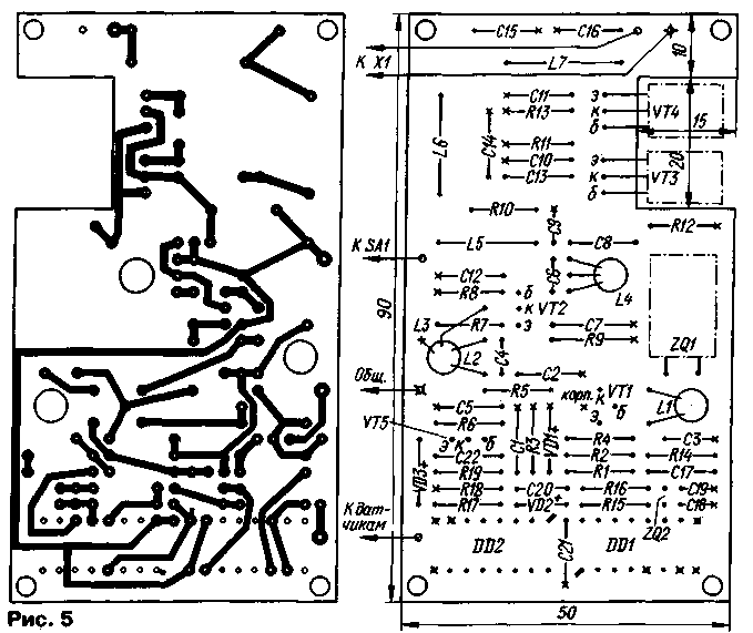
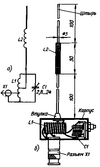
Encyclopedia of radio electronics and electrical engineering/ Automobile. Security devices and alarms The transmitter is assembled on a printed circuit board made of double-sided foil fiberglass 1,5 mm thick. The drawing of the board is shown in fig. 5. On the side of the components, the foil is retained and serves as a common wire. Some of the leads are soldered to a common wire without holes. For the rest of the leads, through holes are drilled and countersinked from the side of the common wire. All solder points to the common wire are marked with crosses in the drawing. The holes for the "grounded" pins of the microcircuits do not need to be countersunk. At the connection points of the board with the X1 antenna connector, power supply and sensors, tinned pins with a diameter of 1 mm are pressed into the holes and soldered. It is convenient to use contacts from the 2PM connector as pins. Transistors VT3 and VT4 are soldered on the side of the printed conductors, the conclusions must first be bent at a right angle. During the final assembly of the transmitter, the transistors are screwed to the metal casing of the device, which serves as a heat sink for them. They are isolated from the casing with thin mica gaskets. The transmitter uses MT and MLT resistors, KM-5 and KM-6 capacitors. The KT315V transistor can be replaced with any silicon low-power npn structure, and the KT368A transistor can be replaced with any of the KT316, KT325 series. Instead of KT646A, transistors of the KT603 and KT608 series are suitable, but you will have to overcome the difficulties of heat removal. Diodes VD2 and VD3 - any low-power silicon. We will replace the KB 110A varicap with KV109, KV124, D901 with any letter index. Quartz resonator ZQ1 - standard, in a flattened metal case, and ZQ2 - in a cylindrical miniature case, from a watch. Coils L1, L2L3 and L4 are wound turn to turn on three polystyrene frames with a diameter of 5 mm, equipped with carbonyl iron trimmers. Coil L1 contains 25 turns of wire PEV-2 0,25, coils L2, L4 - 12 turns, and L3 - 3 turns of the same wire. Coil L3 is wound on top of L2, and L4 has a tap from the third from the top according to the coil scheme. The inductor L5 is wound on a ring of size K10x6x3 made of ferrite 600NN. The winding contains 15 turns of wire PEV-2 0,15. Coils L6 and L7 are frameless, wound round to round on a mandrel with a diameter of 8 mm and contain 5 and 9 turns of wire PEV-2 0,8, respectively. The transmitter is mounted in a metal box measuring 110x60x45 mm. A power switch (SA1), a high-frequency connector SR-50-73FV (X1) and a four-pin 2RM connector (not shown in the diagram in Fig. 1) for connecting a power source and sensors are installed on the walls of the housing. The electrical circuit of a small-sized whip spiral antenna of normal radiation [3], designed for joint operation with a transmitter, is shown in fig. 6a, and its design is shown in Fig. 6b. A small plastic box (its dimensions are not critical) is fixed on the body of the cable block of the SR-50-73FV connector, into which an LC circuit is installed, consisting of an L1 coil and a tuning capacitor C1 with an air dielectric.
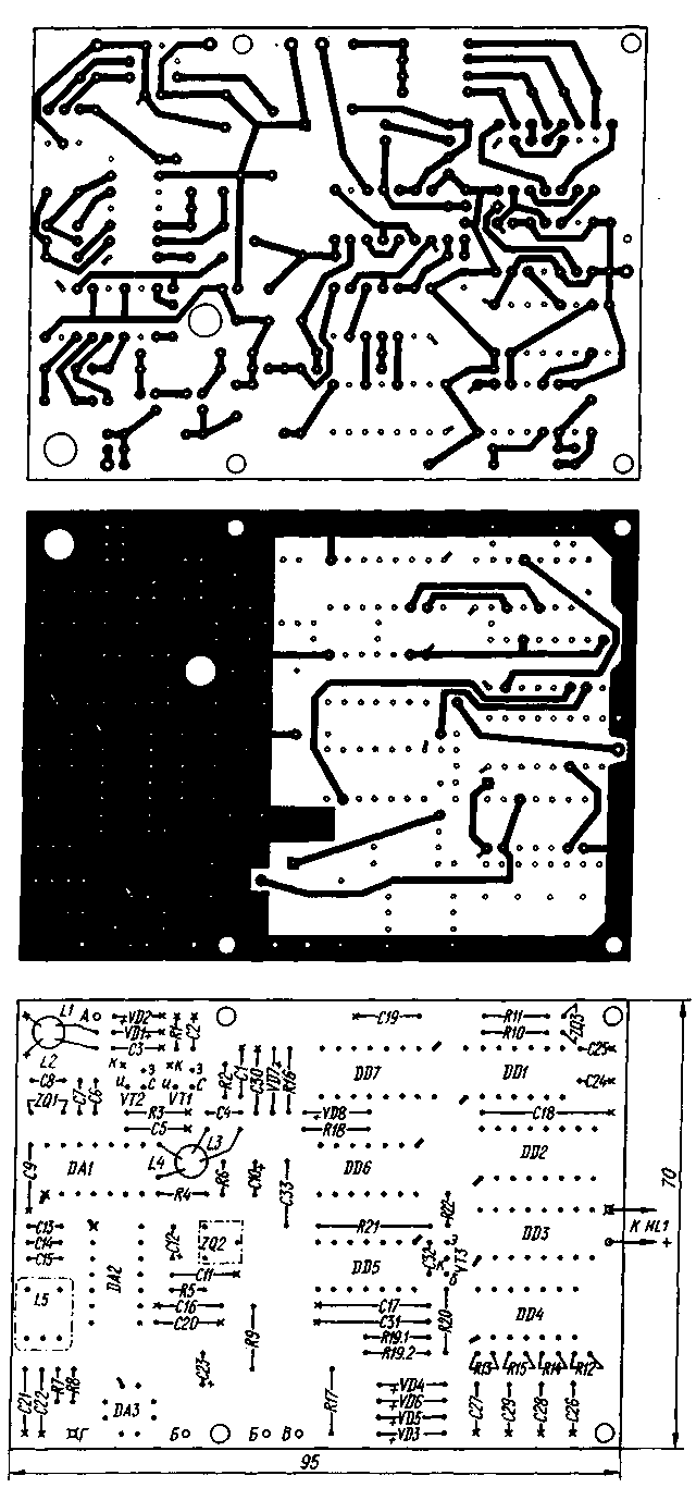
Coil L1 is wound with a pitch of 2 mm with silver-plated copper wire with a diameter of 1 mm on a ceramic frame with a diameter of 10 mm. The number of turns is 15. The locations of the taps are determined when the system is being set up. Capacitor C1 - 1KPVM. The extension coil L2 is wound coil by coil on a frame with a diameter of 6 mm made of organic glass. It contains 130 turns of PEV-2 0,15 wire. At the ends of the frame, two brass pins are fixed on the thread. The lower end of the lower pin according to the drawing is screwed into the hole of a brass bushing fixed on the upper wall of the plastic box. The receiver is assembled on a printed circuit board made of double-sided foil fiberglass 1,5 mm thick. The board drawing is shown in fig. 7. Just like on the transmitter board, under the elements of the high-frequency part of the receiver, the foil is preserved and plays the role of a common wire. The foil frame around the digital node has also been preserved. To connect the board to the antenna, the BF1 sound emitter and the power supply connector, contact pins with a diameter of 1 mm are pressed and soldered into it, just like in the transmitter.
Note that a number of board mounting points related to the digital node need to be soldered on both sides of the board. At two points - they are not round, but square in the drawing - you must first insert short wire jumpers into the holes. The receiver uses resistors MT and MLT; oxide capacitors - K53-19, the rest - KM-5 and KM-6. It is possible to use parts of other types. Transistors KP303B can be replaced with one double-gate, for example, KP350B. Diodes VD1 and VD2 - any silicon high-frequency or pulse, the rest - low-power silicon. Instead of FP1P1-060.1, other piezo filters for this frequency are also suitable, having a bandwidth of at least 3 kHz, for example, FP1P-60, FP1P-61. Quartz resonator ZQ3 - miniature, in a cylindrical case. Coils L1 L2 and L3L4 are wound on two identical polystyrene frames with a diameter of 5 mm, equipped with carbonyl iron trimmers. Coils L2 and L3 contain 18 turns of wire PEV-2 0,33, winding turn to turn. The communication coils L1 and L4 - 3 turns of PEVSHO 0,2 wire each - are wound over their loop ones from the side of the grounded output of the coil L2 and from the side of the output of the coil L3 connected to the positive power wire. The L5 coil is used industrially manufactured with an inductance of 120 μH with a trimmer. It can be wound independently in the SB-9a armored magnetic circuit, the number of turns is 80, the wire is PEV-2 0.1. The board is installed in a plastic case from a pocket receiver with dimensions of 140x80x40 mm. The antenna is telescopic with a length of about 50 cm. An external power supply unit with an output voltage of 12V was used to power the receiver, supplemented by a voltage stabilizer on the KR142EN8A chip and an output oxide capacitor with a capacity of 10 microfarads for a voltage of at least 16 V. To reduce multiplicative interference, both outputs of the secondary winding of the network transformer block are connected to its output negative wire through ceramic capacitors with a capacity of 0,1 microfarads. For autonomous power supply of the receiver, a rechargeable battery 7D-0,115-U 1.1 can be used. The system must be assembled and adjusted in a certain order. First, the digital part is assembled both in the transmitter and in the receiver, but without the resistor R17 in the receiver, and resistors R4, R5 and R7 are additionally installed in the transmitter. The power supply circuits of the transmitter and receiver are connected, the collector of the transistor VT5 of the transmitter is connected to the inputs of the receiver element DD5.1. When the supply voltage is applied, the sound signal may or may not turn on, however, with the arrival of the first transmitter pulse, the HL1 LED should flash for a short time and the signal should sound (or continue to sound). After 16 s, the HL1 LED should flash again, and the signal should stop. Further, the LED should turn on for 1 s every 16 s, and the sound signal should remain off. I Then, in the pause between pulses, the capacitor C31 of the receiver should be closed, which will simulate the transition of the transmitter to continuous mode. An alarm should sound immediately. Open the capacitor C31 and make sure that after passing two pulses from the transmitter (this can be clearly seen from the flashes of the HL1 LED), the sound signal stops. Disconnect the inputs of the element DD5.1 of the receiver from the collector of the transistor VT5 of the transmitter - no later than after 15 s, the signal should sound again. Next, resistors R1-R3, R14 are installed in the transmitter, and R7-R9, R17, capacitors C21, C22 and comparator DA3 in the receiver. At the common point of the resistors R7 and R8 of the receiver, pulses with a frequency of 2 Hz are fed through the button from the common point of the resistors R3 and R1024 of the transmitter. When closing and opening the contacts of the button, the HL1 LED should turn on and off, respectively, with a short delay (it should be noticeable to the eye). If the nodes do not work as described, faults should be sought, as usual, when setting up digital devices - check the operation of quartz oscillators, the correct frequency division in the counters and the formation of the corresponding signals, etc. If, when manipulating the button, a pulse signal with a frequency of 1024 Hz does not the LED turns on, select the resistor R19 and, possibly, R20. For the convenience of the exact selection of the R19 resistor, it is "split" into two parts (and there are places for them on the board), which have a resistance ratio of 9:1. After the complete assembly of the device, the radio channel setup should begin with the transmitter. The emitter and collector of the transistor VT5 are connected with a temporary jumper, and as an antenna equivalent, the transmitter output is loaded with a 51 Ohm resistor with a power of 2 W. At the time of tuning, transistors VT3 and VT4 must be installed on a plate duralumin or copper heat sink with dimensions of at least 100x60 mm. By applying a supply voltage to the transmitter and rotating the L2 coil trimmer, generation is achieved. At the same time, an RF voltage of 2 V should be present on the basis of the VT0,6 transistor. It is measured with a broadband oscilloscope or a high-frequency voltmeter. The buffer stage on the VT2 transistor is adjusted by rotating the coil trimmer 1-4 until the maximum amplitude is obtained on the collector of the VT2 transistor (at least 5 V). At the same time, on the basis of transistors VT3 and VT4 there must be a voltage of at least 2 V. By stretching and compressing the turns of the coils L6 and L7, they achieve the maximum voltage on the antenna equivalent - 10 ... 12 V. The transmitter setting is specified in the same order after it is installed in frame. Then tune the transmitting antenna. In the middle of a metal plate (foiled fiberglass can also be used) with dimensions of at least 250x250 mm, a SR-50-73FV connector socket is installed and connected to the transmitter output with a cable that will connect the antenna to it on the car. Install the antenna with the male part of the connector into the female and turn on the transmitter to work in continuous mode. The measurement maximum is controlled by the field strength indicator. You can use a simple wavemeter [5] by connecting a small microammeter to its output. The circuit L1C1 of the antenna is tuned to resonance for the maximum reading. Next, a tap is selected from the coil towards the transmitter (2 ... 3 turns) and towards the pin (6 ... 10 turns), also achieving the highest field strength. After installing the antenna in the car, the setting of the L1C1 circuit is clarified. To establish the receiver, it is advisable to use a broadband oscilloscope. Work begins with an IF amplifier. A signal with a frequency of 465 kHz with a deviation of 3 kHz is fed to the input of the DA2 microcircuit (pin 13) and the L5C14 circuit is tuned by rotating the L5 coil trimmer until the best squareness and pulse duty cycle equal to two are obtained at the output of the DA2 microcircuit. If self-excitation of the DA2 chip is detected, the L5 coil should be shunted with a low-power resistor with a resistance of 5 ... 10 kOhm. Then check the operation of the local oscillator. If necessary, capacitors C6-C8 are selected until stable generation is obtained at the third mechanical harmonic of the quartz resonator ZQ1. Next, they check the voltage at the source of the transistor VT2, it should be within 0,3 ... 0,5 V. Having applied a signal with an operating frequency to the input of the receiver, by rotating the trimmers of the coils of the L2C3 and L3C4 circuits, tune the circuits into resonance, focusing on obtaining maximum sensitivity receiver (about 0,5 μV). In the absence of a signal generator, it can be replaced by a tuned transmitter without an antenna by loading it with the 51 ohm resistor mentioned above. First, the transmitter is located next to the receiver, and as it is adjusted, the transmitter is moved away to the maximum distance, controlling the signal reception on the oscilloscope connected to the output of the DA2 microcircuit, or by the glow of the HL1 LED. The transmitter is quite economical - a fully charged car battery with a capacity of 55 Ah is enough for three months of its continuous operation in standby mode. The described radio guard has been in operation for more than three years and once already helped prevent intruders from entering the car. A lot of useful information on building a radio channel for a car watchdog and on various design options for transmitter and receiver antennas is contained in publications [1; 6-8]. Literature 5. Golubev O. A simple wavemeter. - Radio, 1998, No. 10, p. 102. Author: S. Biryukov, Moscow; Publication: N. Bolshakov, rf.atnn.ru
Artificial leather for touch emulation
15.04.2024 Petgugu Global cat litter
15.04.2024 The attractiveness of caring men
14.04.2024
▪ The Sahara Desert has expanded significantly
▪ section of the site Labor protection. Selection of articles ▪ article Gardens of Armida. Popular expression ▪ article How do bees communicate? Detailed answer ▪ article Economical heat stabilizer. Encyclopedia of radio electronics and electrical engineering
Home page | Library | Articles | Website map | Site Reviews www.diagram.com.ua |


 Arabic
 Bengali
 Chinese
 English
 French
 German
 Hebrew
 Hindi
Hindi Italian
 Japanese
 Korean
 Malay
Malay Polish
 Portuguese
 Spanish
 Turkish
 Ukrainian
 Vietnamese


 Leave your comment on this article: