|
|
ENCYCLOPEDIA OF RADIO ELECTRONICS AND ELECTRICAL ENGINEERING A new way to generate an SSB signal. Encyclopedia of radio electronics and electrical engineering
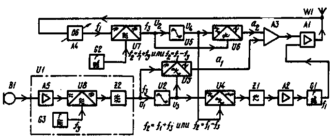
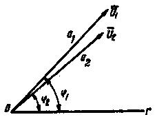
Encyclopedia of radio electronics and electrical engineering / Civil radio communications In amateur radio communication equipment, two methods of forming a single-sideband signal are widely used - filter and phase [1]. The third - phase-filter has not yet received distribution. All of them belong to the "direct" methods, which are characterized by the fact that the audio signal after a series of frequency transformations turns into a single-sideband. A special place is occupied by the "synthetic" method of forming an SSB signal, proposed by M. Verzunov [2]. Its essence is as follows. An SSB signal is formed from the original audio signal (by any method) at a relatively low auxiliary frequency, where it is easy to suppress the carrier and unnecessary sideband. The generated signal is detected by two detectors - amplitude and frequency, at the output of which voltages are allocated that are proportional to the instantaneous amplitude and instantaneous frequency of the SSB signal. The master oscillator of the transmitter, excited at the operating frequency, is modulated in frequency by the voltage from the output of the frequency detector. In the output stage of the transmitter, the emitted signal is also modulated in amplitude by the voltage from the output of the amplitude detector. With correctly selected modulation coefficients, a normal SSB signal is formed and enters the antenna at the operating frequency. The advantages of the "synthetic" method include the possibility of generating an SSB signal at an arbitrarily high frequency and a low content of by-products (combination frequencies) in the output signal. In addition, most RF transmitter stages can operate in Class C mode with high efficiency. The disadvantages of the method include the inadmissibility of the relative phase shift of the control signals in the frequency and amplitude modulation channels and the need to accurately reproduce the amplitudes and frequencies of the synthesized signal, which imposes stringent requirements on the linearity of the amplitude-frequency characteristics of detectors and modulators. The last disadvantage in the frequency channel is partially eliminated when the PLL system is used to control the frequency of the master oscillator. Relatively recently, brief reports appeared in the press about the development in England of a new scheme for generating an SSB signal by a "synthetic" method using automatic control technology [3], which made it possible to largely eliminate the described disadvantages of the method. The authors (V. Petrovic and W. Gosling) called the new transmitter "Polar loop SSB transmitter", meaning, most likely, a vector representation of the SSB signal in polar coordinates. The block diagram of the transmitter is shown in fig. one. Its high-frequency part is simple - it contains a master oscillator G1 tuned to the operating frequency f, and a power amplifier A1 connected to the antenna W1. The low-frequency part of the apparatus is more complicated. It includes an auxiliary SSB signal generator U1, which converts the audio signal from microphone B1 into single-band at some relatively low frequency, for example 500 kHz. Shaper U1 may contain microphone amplifier A5, balanced modulator U8. reference oscillator G3 at a frequency of 500 kHz and electromechanical filter Z2. The generated low-frequency SSB signal Ui is fed to the limiter U2 and the synchronous detector U3, at the output of which a voltage is generated. proportional to the amplitude of the SSB signal a1. Thus, elements U2 and U3 perform the functions of an amplitude detector. Of course, a conventional envelope detector could also be used, but its linearity is worse, and the limiter is still needed for further signal transformations. Now let's look at the block diagram of the transmitter "from the other side", from the output. Part of the output RF signal through the attenuator A4 is fed to the frequency converter U7, the local oscillator of which is the frequency synthesizer G2 or some other highly stable generator. Its frequency f is set equal to the difference or sum of the operating frequency f1 and the auxiliary low frequency f3. In this case, after conversion, a signal with a frequency equal to the frequency of the generated low-frequency signal (in our example, 500 kHz) will be selected. Assume that the operating frequency f1 is 28 kHz. then the G500 synthesizer frequency should be 2 or 28 kHz. The converted signal is applied to the limiter U000 and the synchronous detector U29. similar to nodes U000 and U5. A voltage is generated at the output of the synchronous detector U6. proportional to the amplitude of the emitted signal a2. Both voltages, a3 and a6, are applied to the differential mode of the DC modulation amplifier A2 and control the amplitude of the RF signal in the power amplifier A1. Thus, a closed loop for tracking the amplitude of the emitted signal is formed. The operation of the loop is little affected by the transmission coefficients of synchronous detectors and other links. Moreover, the greater the gain in the loop (determined mainly by amplifier A3), the more accurately the amplitude of the output signal is tracked, provided that the phase shifts of the control signal in the loop are small (otherwise the loop may self-excite). The required peak output power of the transmitter is set by the attenuator A4. Consider the operation of the frequency tracking channel. Clipped SSB signal From and the frequency-converted and also clipped output signal U4 is fed to the phase detector U4, where they are compared with each other in phase. The output voltage of the phase detector. proportional to the phase difference, through the low-pass filter Z1 and the DC amplifier A2 acts on the varicap included in the circuit of the master oscillator of the transmitter G1. Nodes U4, Z1. A2 and the varicap are thus included in the PLL loop, which establishes the exact equality of the frequencies of the auxiliary SSB signal with the converted output. It is only necessary that when the transmitter is turned on, the frequency of the master oscillator falls into the PLL loop capture diarrhea (which can be tens and hundreds of kilohertz), further tracking occurs automatically. During pauses in the speech signal, the system adjusts to the frequency of the suppressed carrier f3, the remainder of which is available at the output of the auxiliary SSB signal shaper U1. The output stage of the transmitter is closed during pauses due to the operation of the amplitude tracking loop. The essence of the operation of the entire system, therefore, boils down to the following: an auxiliary SSB signal is formed at frequency f3 (by node U1), the emitted signal is converted to the same frequency (elements U7, G2), and two automatic tracking loops for amplitude and frequency establish equality of amplitudes and phases of the auxiliary and radiated SSB signals. As a result, an SSB signal is emitted that is exactly the same as the auxiliary signal, but at a much higher frequency f1. The operation of the system can also be explained by a vector diagram in polar coordinates r and φ, shown in Fig. 2.
Vector U1 represents the auxiliary SSB signal. The length a of this vector corresponds to the amplitude, and the angle φ1 corresponds to the phase. The frequency-converted output of the transmitter is shown as the vector U2. The amplitude control system seeks to establish the equality of the lengths of the vectors U1 and U2, and the PLL system - the equality of their phases. With perfect tracking, the vectors match and the converted signal exactly matches the generated signal. There is almost always some tracking error, which decreases as the gain in the control loops is increased. When implementing the RF part of the transmitter, it turns out to be extremely simple. The output stage can operate in class C mode with high efficiency. High linearity of amplitude and frequency modulators is also not required, since deep negative feedback in the control loops linearizes the system and significantly reduces non-linear distortions. There are also no special requirements for the stability of the master oscillator G1, since its frequency is stabilized by the PLL system. The transmitter is tuned in frequency by the synthesizer G2. The inventors of the new "synthetic" method report that the HF part of the transmitter is completely insensitive to supply voltage ripples, changes in element ratings, etc. The main advantage of the transmitter is the very high purity of the output spectrum, which is especially important in modern air conditions. The transmitter does not emit side frequencies (except for harmonics). When tested with a two-tone signal, the level of spurious components was found to be below -50 dB. and in conventional filtered SSB transmitters it rarely drops below -30...-35dB. The transmitter was tested at a frequency of 99.5 MHz with a radiated power of 13...20 W. It seems that the new method of forming SSB will interest radio amateurs with high quality parameters. The possibility of "transceiverization" of the described transmitter is also being considered. For example, elements U7 and G2 (see Fig. 1) can serve as a frequency converter for the receiving part of the transceiver. When receiving, the usual IF amplification path and the SSB detector are connected to the output of the U7 converter, and the reference signal for the latter can be taken from the auxiliary SSB signal generation unit U1. It is also possible to double convert the received frequency f1 and the frequency f3 using the first quartz and second tunable local oscillators, as is often done in amateur radio receivers and transceivers. The entire SSB signal generation system will work in this case on the second IF of the receiver. Literature
Author: V. Polyakov (RA3AAE) Moscow; Publication: N. Bolshakov, rf.atnn.ru
A New Way to Control and Manipulate Optical Signals
05.05.2024 Primium Seneca keyboard
05.05.2024 The world's tallest astronomical observatory opened
04.05.2024
▪ The world's oceans have become deeper by 8 centimeters ▪ High-voltage intelligent power modules with increased current carrying capacity
▪ section of the site For a beginner radio amateur. Article selection ▪ article Euclidean geometry. History and essence of scientific discovery ▪ article What does moon dust smell like? Detailed answer ▪ Paramedic article. Job description ▪ article Brown mordant for iron and steel things. Simple recipes and tips
Home page | Library | Articles | Website map | Site Reviews www.diagram.com.ua |


 Arabic
 Bengali
 Chinese
 English
 French
 German
 Hebrew
 Hindi
Hindi Italian
 Japanese
 Korean
 Malay
Malay Polish
 Portuguese
 Spanish
 Turkish
 Ukrainian
 Vietnamese


 Leave your comment on this article: