|
|


 Arabic
 Bengali
 Chinese
 English
 French
 German
 Hebrew
 Hindi
Hindi Italian
 Japanese
 Korean
 Malay
Malay Polish
 Portuguese
 Spanish
 Turkish
 Ukrainian
 Vietnamese
|
ENCYCLOPEDIA OF RADIO ELECTRONICS AND ELECTRICAL ENGINEERING Amateur modular mixing console. Encyclopedia of radio electronics and electrical engineering
Encyclopedia of radio electronics and electrical engineering / Musician This simple remote control can be made almost at home or at school. Nevertheless, the capabilities of this remote control are sufficient to work in the school assembly hall, when scoring outdoor concerts or recording small musical ensembles. The device can be powered both from AC mains and from batteries. The mixing console "MICRO RTV", which is described in [1], is not easy to manufacture in amateur conditions. This article proposes a simplified version of a modular stereo console (outputs AUX, INSERT excluded), designed without the use of scarce microcircuits. Some reduction in the requirements for the depth of processing of input signals and the number of channels is quite justified and acceptable, since it is not intended for studio conditions and very high technical parameters are practically not needed. However, the modular design of the remote control allows you to quickly transform it to solve various tasks, and the ability to operate it from a mains adapter or a 12 V battery expands its scope. The proposed design, when powered by a 12 V battery, is safe even for children and can be used at school discos or when performing children's ensembles. And when traveling "to nature" you can, for example, connect to a car battery through the "cigarette lighter". Batteries can be placed under the boards at the bottom of the remote control, allowing it to work autonomously for some time. The block diagram of the device is shown in fig. 1, and a possible design option for the front panel of the remote control is on the photo of the first page of the cover.
The input six modules are selected depending on the required tasks. For this, several variants of input blocks have been developed. A microphone module (its diagram is shown in Fig. 2a) with a CANNON (XLR) input connector used with professional microphones. This block is convenient for vocalists; it allows you to amplify the signal from a microphone with a voltage of 1 ... 240 mV (with a signal-to-noise ratio of 60 dB and Kr = 0,2%). The module has a gain control (variable resistor R3) that changes the sensitivity of the amplifier by 14 dB, a panoramic control "PAN" (R35), as well as output signal level (R25) and tone controls for high and low frequencies (respectively R17 and R19). At frequencies of 30 Hz and 15 kHz, the depth of tone control reaches ±12 dB. The overload indicator LED - red LED - lights up when the level is 2 dB below the allowable level.
The module has quite decent technical parameters and is slightly inferior in operation to the corresponding modules of professional consoles. The balanced input significantly reduces the level of external noise when using a long microphone cable. By removing the jumper between points a and b, it is possible to connect "phantom" power for condenser microphones. But, given that there is simply nowhere to get a voltage of 48 V from the console itself, only dynamic microphones are supposed to be used. They are much stronger than mechanical ones, that is, they are not afraid of shocks, shaking and, most importantly, are much cheaper. Even professionals use condenser microphones only in studio conditions. Unfortunately, due to the relatively low supply voltage, the overload margin of the microphone amplifier is only about 16 dB, but when using dynamic microphones, especially if you are not very fond of frequency correction (raising low or high frequencies), this margin is quite enough. The first stage (DA1) is assembled on the LM381 chip (the domestic analogue is K548UN1A). Resistors with a spread of no more than ±1% should be used in the input circuit. The selection of resistors R6 and R7 is necessary in order to obtain a constant voltage at the outputs of the microcircuit, close to half the supply voltage. A significant difference in the resistance of the selected resistors can affect the symmetry of the input, so it is better to choose chips with a small spread in DC mode. The remaining cascades are made on a quad op amp of the TL084 type (TL074 or K1401UD4). Exceeding the maximum allowable level marks the red LED HL1. The response threshold of the two-way comparator DA2.3 is selected by selecting the resistor R22. It is better to set it slightly below the maximum allowable signal level (recommended by 2...3 dB). The current consumed by the module is 18...20 mA. The universal input module is a kind of microphone amplifier, since it has the same circuit and parameters, but a JACK 6,3 connector and a sensitivity switch are installed at the input (differences in the module circuit are shown in Fig. 2, b). With a decrease in gain, the input impedance of the amplifier simultaneously increases by 10 times to 30 kOhm. These blocks are very convenient for vocal and instrumental ensembles. This connector is used to connect many microphones; An electric guitar can also be plugged into this jack by turning the switch to the "high" (level) position. A linear two-channel amplifier with unbalanced inputs (a diagram of this module is shown in Fig. 3) is convenient for amplifying stereo signals from an external phonogram playback device: player, tape recorder, player.
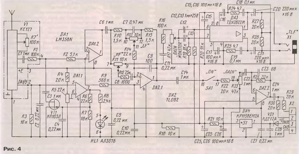
Connecting an electric guitar to one of the stereo input channels would disrupt stereo imaging. Therefore, such modules are designed for consoles used in discos, dance floors, when several external sound signal sources are connected to the system at the same time. The module allows you to adjust the tone of the sound at low and high frequencies (at frequencies of 30 Hz and 15 kHz, the adjustment range exceeds 30 dB), as well as gain and balance. Input impedance - more than 20 kOhm. The normalized value of the output signal voltage of 240 mV can be obtained if the input signal has a voltage in the range of 20 mV ... 3 V. The highest output voltage is at least 3 V. The only difference from conventional circuits is the inclusion in each channel of the same a microphone amplifier, an additional link R1C9 (R2C10), which significantly reduces the noise level due to a slight (by 2 dB) reduction in high-frequency boost. The coefficient of non-linear distortion does not exceed 0,2%. Signal-to-noise ratio - not less than 70 dB. The current consumed by the module reaches 40 mA, which must be taken into account when powered by batteries or a low-power AC adapter. Another version of the input module is using a small-sized tuner with the VHF-2 (FM) range for communication with the radio microphone. Although inexpensive radio microphones work at distances up to several tens of meters, they are very convenient due to the absence of wires. Ordinary radio receivers are of little use for this purpose due to high noise in the absence of a transmitter carrier frequency. Therefore, a module was developed on the basis of the tuner from the KE127 radio designer of the Kaskad company (see the diagram in Fig. 4). Its structure includes a noise suppressor [3] DA1 (LM358N), a tone block with high and low frequency control on DA2.1 (TL082) and a control amplifier (DA3) with a level control. The signal from the tuner is controlled through headphones plugged into the "TLF" jack (JACK 3,5). After tuning the tuner to the frequency of the radio microphone, in the absence of interference, the signal through the toggle switch "ON" from the amplifier DA2.2 can be fed to the busbars of the console (MIX1, MIX2). The "GAIN MONITOR" control (R17) provides independent control of the listening volume. In the control amplifier, the inputs of the two channels are combined, since the receiver of signals from the radio microphone does not need to provide stereo sound.
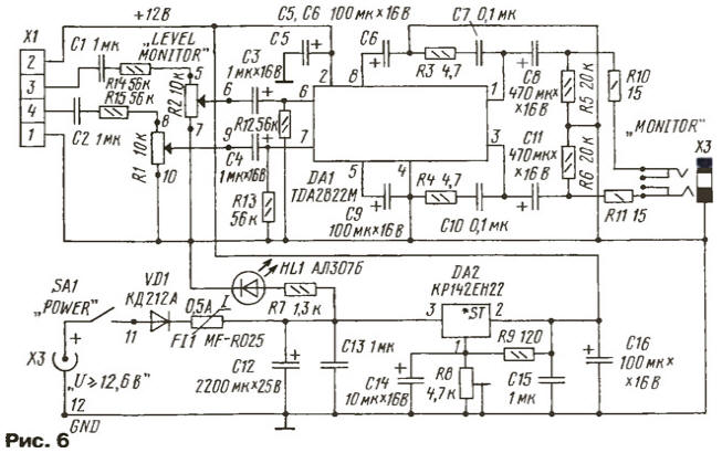
The tuner can also be used for its intended purpose by turning on the reception of a broadcast radio station during a break in some events. It should be noted that the tuner of the KE-103 radio designer can also be used for the module, in which the sensitivity is somewhat lower due to the lack of an additional radio frequency amplifier. Some drawback of the radio microphone module is a rather high current consumption when battery powered - about 40 mA (even at minimum volume). Before installing the tuner board, you should check for the presence of a 100 kΩ resistor at the low-frequency output. It is also advisable to replace the 4,7 uF oxide capacitor in the same circuit with a ceramic capacitor with a capacitance of 0,22 ... 1 uF. This circuit in the tuner is designed to output a complex stereo signal (CSS), and a jumper is often installed instead of a resistor. The tuner tuning variable resistor is replaced with a variable resistor (for example, type SPZ-4) installed on the front panel of the module. To control the noise suppressor, you need to connect pin 9 of the K174XA34 chip with pin 2 of the board with a wire. The response threshold of the DA1.1 noise suppressor comparator is chosen by adjusting the resistor R5: you can reduce noise in the absence of the carrier frequency of the transmitter or even "suppress" the signal when the carrier level drops below the selected level. When the squelch is turned on, the red indicator HL1 is lit. In the module, the tuner board is fixed on the corners (from the side of the components located on it), and the variable resistor R17 is placed between the main board and the tuner board. In addition to the input modules, the console has two output modules "MASTER", assembled according to the same scheme (Fig. 5). Each of them has a totalizer (DA1.2), a "LEVEL" output level control and an LED ten-level quasi-peak level meter, basically meeting the requirements of the second type of professional level meters, i.e. have an integration time of 5 ms and a return time of about 3 s [2]. The output signal levels are controlled in the range from -20 dB (0,1 of the nominal value) to +3 dB (1,41 times higher). In the area from -3 dB to +3 dB, the scale error does not exceed 1 dB, which makes it easier to control signal levels when they are close to the normalized value. With the "0" regulator brought out under the slot, it is possible to select the nominal value of the output voltage from 240 mV to 1,55 V.
Four outputs can be used in the console: two - from the "MASTER" modules and two - from the "MONITOR" ("TLF") connector. If necessary, it is permissible to connect a long connecting line to the "MONITOR" outputs. A level meter is not connected to these outputs, but the quality parameters make it possible to use them both for listening to the signal and for feeding it to the input of an amplifier or sound recording device. At Uout. nom = 0,775 V signal-to-noise ratio exceeds 75 dB, and Kg - no more than 0,04%. Without a signal, the current consumption of the output module is 16 mA; on the signal, when the meter's LEDs are on ("dot" glow), the current increases to 28 mA. Setting up the module comes down to setting the indicator to "0" dB using the trimmer resistor R8 when the signal reaches the nominal level. Unlike most "household" consoles, where at best there is an indicator of average values, the quasi-peak meter can control the maximum levels of the output signal. The output line uses op-amp chips (DA1) of the TL082 (or TL072) type, and the level meter uses the LM3914. The signal level is marked with a luminous dot. For the "column" indication mode, it is enough to connect the points "a" and "b" with a wire; this will increase the current consumed by the board. It is advisable to use the upper LEDs that indicate overload (HL8-HL10) in red, HL7 in yellow, and the rest in green (all from the KIPMO series). Other types of LEDs can be used as long as the color difference is maintained. The detector of the meter is made on a specialized chip K157DA1 (DA2). The second channel of the microcircuit is not used. The DA3 voltage regulator is assembled on KR1158EN12 or KR1170EN12, but when manufacturing a block for use only in the remote control, it is permissible to put a jumper instead of a microcircuit. In order to provide the ability to supply voltage from the adapter or from the battery to the module or board directly, for example, when connecting the microphone module directly to an external power amplifier, the boards of each of the blocks are provided with their own voltage stabilizers. If the module is intended only for installation in the console, then a jumper is installed instead of the integrated stabilizer chip. Since most network adapters have an unstabilized rectified voltage at the output, the remote control has its own internal voltage regulator (DA2 in Fig. 6), which already operates at a voltage of only 0,6 V, exceeding 12 V. Taking into account the voltage drop across the protective diode a rectified voltage of at least 13,2 V must be supplied to the remote control. Adapters with the switch set to the "+12 V" position usually provide an output voltage of 15 ... 17 V, and charged acid batteries - 13,4 V. When installed a battery charger and a low battery LED signaling device can be built into the battery panel in the power supply module.
Together with the voltage stabilizer, the control module contains a two-channel amplifier "MONITOR" ("TLF") with independent gain control in each channel. The TDA2822M chip (its output power is 2x1 W) allows you to connect adapter head connections to its outputs. The supply voltage is supplied through a protective diode VD1 and a self-restoring fuse FI1 type MF-R025 for a current of 0,5 A. The signal is taken through the JACK 6,3 connector, and the printed circuit board wiring allows three types of commercially available connectors to be installed on it. The basic design is designed for the installation of nine modules, so the steel case has dimensions of 280x183x65 mm. The remote control can be placed on the table or hung on the wall, where it will not disturb anyone. The right side panel has a connector for switching on a network adapter with a rectified output voltage of 12,6 ... 16 V. Individual blocks (modules) are 30 mm wide, each of them is connected to the other modules through a connector and fixed in the case with two screws. In most cases, given the ability to quickly replace blocks depending on emerging needs, nine modules are usually sufficient, and adapters with a maximum load current of at least 0,5 A provide power for this number of blocks. If necessary, you can design the case with other sizes. It is also obvious that module boards can be installed in other equipment as usual radio designer boards. Particular attention should be paid to the choice of adapter. It must be borne in mind that many of them simply cannot provide the declared current. There are adapters with 10 V filter capacitors, although the operating voltage on them exceeds 15 V. There are even adapters with a "stabilized" output voltage on sale, which not only do not have a stabilizer, but even a capacitor! A sufficient idea of the design is given in Fig. 7, which shows a sketch assembly drawing of one of the input modules of the console.
The modules are attached to the upper and lower U-shaped walls of the housing with M2.5 screws. For wall thicknesses greater than 1 mm, the mounting holes can be threaded directly into the housing itself. To fasten the boards to the front panels, 5 mm wide corners are used, which are bent from the same steel; they also have M2.5 threaded holes. All boards are connected to the cross-board with busbars via MPN-4 connectors. The bottom of the case with holes for cooling and for wall mounting screws can be thinner. Legs are screwed to it for installation on a table. The proposed design allows you to make a remote control even at home. All printed circuit boards of the remote control are made of one-sided foil textolite, so jumpers are used in some places. A little about the modifications of the console. For example, there is a simple way to dramatically expand the capabilities of the device. To do this, two more additional buses "MIX3" and "MIX4" should be placed on the busbar board, and pushbutton switches (SB1, SB2 in Fig. 8) should be placed under the input modules, which will allow you to send a signal from these modules to the "MIX1" buses, "MIX2" or "MIX3", "MIX4".
A simple parallel connection of the busbars can be provided. At the same time, the buttons on the side wall of the remote control do not interfere with the installation of the remote control on a table or mounting on a wall, but it becomes possible to use a number of modules ("SERVICE MODULE") - means of dynamic and frequency signal processing. These can be limiters (limiters), compressors, expanders, various noise suppressors, reverbs or multi-band equalizers and other devices. The capabilities of such a console, even with a small number of channels, will be quite sufficient even for a demanding sound engineer when working in outdoor conditions. The front cover of the magazine shows the exterior of a homemade monophonic modular console designed for a sound reinforcement system. It is possible to develop a version of the console with a 2x22 W two-channel power amplifier block, reducing the number of input channels. But such a remote control will consume up to 4 A, and a conventional adapter will not be enough, and a more powerful connector will be required to supply the supply voltage. Such a "transforming" console will be very convenient, since it is possible to easily change its configuration depending on the emerging tasks and easily upgrade it. With multiple interchangeable units, you can get the most out of your remote at meetings, discos, and concerts. By the way, modular design is also promising for creating amateur combined measuring instruments with interchangeable blocks. PCB drawings and design of console modules Drawings and drawings of boards are given in the shell of the Circad design system. The demo version of the program is shareware and is available at circad.net. Literature
Author: E.Kuznetsov, Moscow
Artificial leather for touch emulation
15.04.2024 Petgugu Global cat litter
15.04.2024 The attractiveness of caring men
14.04.2024
▪ PENTAX Stops Production of Compact and SLR Analog Cameras ▪ ASUS TUF Sabertooth Z97 and Gryphon Z97 Motherboards ▪ A new flexible type of battery for wearable electronics
▪ section of the site Tools and mechanisms for agriculture. Article selection ▪ article Let the genie out of the bottle. Popular expression ▪ article How much carbon dioxide is on the planet? Detailed answer ▪ article How to apply a support bandage. Health care ▪ article Uyghur proverbs and sayings. Large selection
Comments on the article: a guest How to apply a variable resistor and high-frequency and low-frequency sound to the TDA-2822 chip in the circuit.
Home page | Library | Articles | Website map | Site Reviews
www.diagram.com.ua |


 Leave your comment on this article: