|
|


 Arabic
 Bengali
 Chinese
 English
 French
 German
 Hebrew
 Hindi
Hindi Italian
 Japanese
 Korean
 Malay
Malay Polish
 Portuguese
 Spanish
 Turkish
 Ukrainian
 Vietnamese
|
ENCYCLOPEDIA OF RADIO ELECTRONICS AND ELECTRICAL ENGINEERING MIDI keyboard on PIC16F84. Encyclopedia of radio electronics and electrical engineering
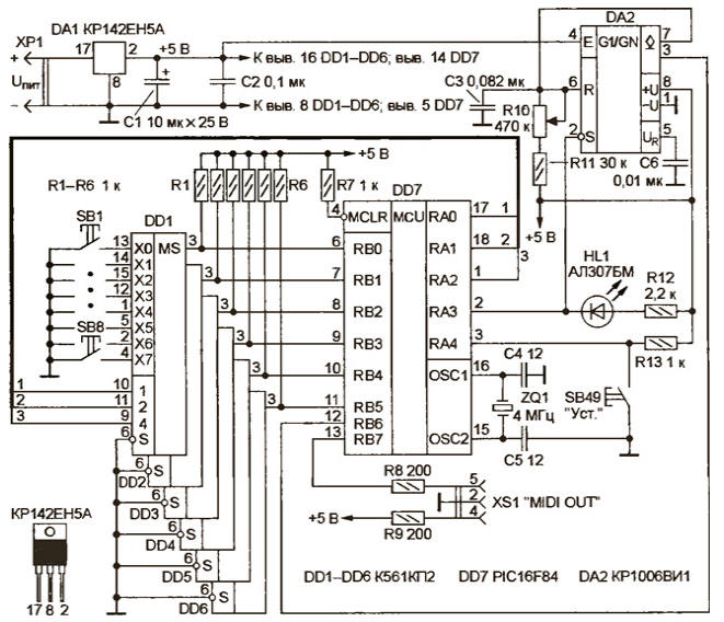
Encyclopedia of radio electronics and electrical engineering / Musician The proposed 48-key MIDI keyboard is designed to work in conjunction with a personal computer (PC) or keyboardless synthesizers. It serves 16 MIDI channels. The built-in knob can be used to either control the volume or manipulate one of the 31 controllers. The use of the PIC16F84 microcontroller (MC) made it possible not only to simplify the device circuit, but also to significantly reduce the cost and complexity of execution, abandoning the traditional i8051 MC in this area. Schematic diagram of the proposed MIDI keyboard is shown in the figure. Its basis is MK DD7, which performs the basic operations of polling all manipulators and organizing a MIDI interface. Multiplexers DD1-DD6 are designed to implement dynamic key polling. Eight subkey contact groups are connected to each of them, and the signal from the output is fed to the corresponding input of port B of MK DD7 (only DD1 is fully shown in the diagram, the rest are switched on in the same way).
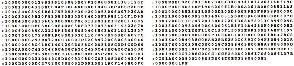
The volume control - a variable resistor R10 - is included in the RC circuit of a single vibrator assembled on a DA2 timer. The position of its engine is determined by the duration of the pulses received at the input of RB6 DD7. The single vibrator is triggered by pulses coming from the RA3 output, which simultaneously controls the operating mode indicator - the HL1 LED. The program that controls the operation of the MK DD7 polls the keyboard. As soon as a key press or release is detected, a procedure is called that sends the corresponding MIDI message [1]. Since the PIC16F84 does not have a built-in universal asynchronous serial transceiver (UART), the program implements the software organization of the MIDI interface using simple shift operations. When calculating the position of the slider of the resistor R10, its configuration as a controller manipulator or as a volume control is taken into account. In the first case, the read value is compared with the poll recorded in the last cycle, and if the difference is established five times in a row, then the corresponding MIDI message is sent. The position of the R10 resistor slider is digitized by the controller into a five-bit code, and thus the device is sensitive to its 32 different positions. If R10 is "configured" as a volume control, the necessary information is sent along with keypress events. With the SB49 button, the device is switched to the configuration mode, as indicated by the HL1 LED. In this case, no keystroke messages are sent to the output of the device. Pressing any of the first 16 keys (i.e., connected to the DD1 and DD2 multiplexers) switches the MIDI channel, any of the 32 others selects the corresponding controller number, which will be controlled by the R10 resistor. If the SB17 key is pressed (its contact is connected to the X0 input of DD3), R10 is configured as a volume control, otherwise (by pressing SB18, SB19, etc.) - as a MIDI-koh-troller keypad, the number of which is assigned by pressing the SA18-SA48 keys (SA18 - controller O, SA19 - controller 1, etc.). Program codes in the form of a hex-file are shown in the table. The first byte of line 9 (number 29h) is a constant that specifies the number of the note from which the keyboard starts. In the author's version, the initial note is F3 - F of the third octave (note number 41, accepted in MIDI messages). If you use a different keyboard, you should correct this constant and recalculate the checksum of line 9. The source code of the program and some other additional materials for the article
The printed circuit board for the device was not developed - Most of the parts (microcircuits DD7, DA1, DA2, resistors, capacitors, quartz resonator) are mounted on a breadboard, all connections are made with MGTF wire. To reduce the length of the harness going to the key contacts, multiplexers DD1-DD6 are installed directly under the keyboard. The power supply connected to the XP1 connector must have an output voltage of 6 ... 12 V at a current of about 50 mA. With minor modifications, K561KP2 (DD1-DD6) can be replaced by K561KP1 multiplexers. In addition to the PIC16F84 MK, the PIC16F84A or PIC16CR84 can be used in the device. Direct replacement with PIC16C84 or PIC16F83 is not possible. As R10, you can use any variable resistor indicated on the resistance diagram with functional characteristic A. The XS1 socket is a standard five-pin ONTS-VG-4-5 / 16-r (DIN-5). The keyboard practically does not need to be adjusted and, if the parts are in good condition and there are no installation errors, it starts working immediately after turning on the power. If the position of the slider of the resistor R10 is determined incorrectly, you should select the capacitor C3 and the resistor R11. If you have a sequencer program, you can connect the keyboard to a PC and check the correct operation of the device as a whole. To connect to a PC, an adapter is used that provides optoelectronic decoupling of the interface, for example, similar to that described in [2]. If you constantly use the keyboard with a PC, you can use the switching converter [3] for power supply by connecting it to the +5 V source of the game port. To reduce the current consumption of R12 in this case, it is advisable to replace it with a resistor of higher resistance or to exclude the HL1 LED altogether. Literature
Author: A.Borisevich, Sevastopol, Ukraine
Artificial leather for touch emulation
15.04.2024 Petgugu Global cat litter
15.04.2024 The attractiveness of caring men
14.04.2024
▪ Platinum atoms oxidize carbon monoxide at room temperature ▪ Clothes with memory will adapt to the owner ▪ MSP430 with Full-Speed USB 2.0 ▪ A new way to pasteurize milk
▪ site section Power regulators, thermometers, heat stabilizers. Article selection ▪ article On the thief's hat is on fire. Popular expression ▪ article Kupen pharmacy. Legends, cultivation, methods of application ▪ article Carrot Sprayer. physical experiment
Home page | Library | Articles | Website map | Site Reviews
www.diagram.com.ua |

 Leave your comment on this article: