|
|


 Arabic
 Bengali
 Chinese
 English
 French
 German
 Hebrew
 Hindi
Hindi Italian
 Japanese
 Korean
 Malay
Malay Polish
 Portuguese
 Spanish
 Turkish
 Ukrainian
 Vietnamese
|
Multi-command telecontrol system. Encyclopedia of radio electronics and electrical engineering
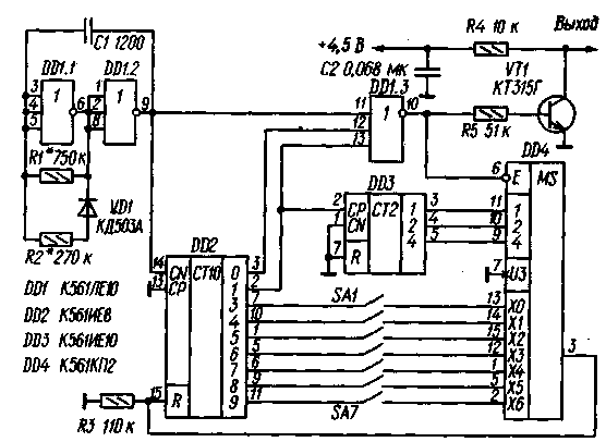
Encyclopedia of radio electronics and electrical engineering / Radio control equipment The encoder and decoder, which will be discussed in the article, allow you to create a telecontrol system with the simultaneous transmission of up to seven discrete commands. Both devices are fully CMOS and therefore very economical. To transmit commands, a number-pulse code is used (for the operation of a number-pulse encoder and decoder, see the article by A. Proskurin "Discrete telecontrol equipment" - Radio, 1989, No. 4, pp. 29-31.) Seven commands transmitted in each cycle of work in turn , correspond to packs of one to seven pulses. If instead of one of them a burst of eight pulses is transmitted, then this means that this command is missing. Schematic diagram of the encoder is shown in fig. 1, and signal diagrams at its characteristic points - in the upper part of Fig. 2. The encoder consists of a square-wave generator, an encoder and an output transistor switch. In turn, the encoder contains two counters (one of them with a decoder), a multiplexer, seven switches (according to the number of commands) and a key on the OR-NOT element.
The generator is made on the elements DD1.1 and DD1.2. The pulse repetition frequency is about 1 kHz. Since the switching voltage of the CMOS elements is not equal to half the supply voltage, the R2VD1 circuit is introduced into the generator to balance the pulses. The generator pulses are fed to the input of a decimal counter with a decoder DD2 and one of the inputs of the key, which is used element DD1.3. In the zero and single states of the counter, at the corresponding outputs of the decoder (pins 3 and 2 of DD2), there is a voltage with a logic level of 1, which prohibits the passage of generator pulses through the DD1.3 element to an electronic key made on the transistor VT1.
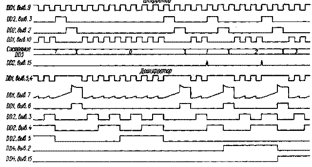
In all other states of the counter, the positive polarity pulses generated at the output of this element under the action of the generator pulses periodically open the transistor VT1. As a result, pulses of negative polarity are formed on its collector, which can be transmitted via a wired or radio link to a telecontrol system decoder. An RF oscillation generator or radio control system modulator can be included in the collector circuit of this transistor. If none of the control switches SA1 - SA7 is closed, the DD2 microcircuit counter operates with a conversion factor of 10, and at the output of the DD1.3 element, bursts of eight pulses are formed, separated by intervals equal to 2,5 generator oscillation periods. Let us now assume that the contacts of any two switches are closed, for example, SA2 and SA3. We will consider the work of the encoder, starting from the moment when the counter DD3 is in the zero state. In this case, the output of the multiplexer DD4 (pin 3) is connected through its internal keys to the input X0 (pin 13), but since the switch SA1 is not closed, this does not affect the operation of the counter DD2 and it performs the entire counting cycle. At the beginning of the next cycle, when the output 1 (pin 2) of the counter DD2 ends with a positive polarity pulse, the counter DD3 switches to state 1 and the output of the multiplexer DD4 is connected to its input X1. The latter, as can be seen from the diagram, is connected through the SA2 switch to pin 10 of the DD2 counter, therefore, when it enters state 4, the logic 1 voltage through the DD4 multiplexer enters the input R and returns it to the zero state. As a result, a burst of two pulses is formed at the output of the element DD1.3, and the counter DD2 starts a new counting cycle. In it, the counter DD3 goes to state 2, the output of the multiplexer is connected to the input X2, the signal to set the counter DD0 to 2 goes to its input R after the transition to state 5, and a burst of three pulses is formed at the output of the device. After the completion of the formation of the eighth burst of pulses, the cycle of the encoder is repeated. The maximum cycle duration at a pulse repetition rate of 1 kHz is 80 ms; when commands are given, it is somewhat less. The schematic diagram of the decoder is shown in fig. Z. and diagrams of signals - in the lower part of fig. 2. The device consists of a pulse shaper, a pause detector, a pulse counter, a register, a decoder, and seven (according to the number of commands) shapers of control signals.
The pulse shaper is made on the element DD1.1, resistor R1 and capacitor C1. The device has the properties of an integrating circuit and a Schmitt trigger. Its output pulses are somewhat delayed relative to the input ones and have a steep edge, regardless of the duration of their edge. In addition, such a shaper suppresses impulse noise of short duration. The pause detector is formed by element DD1.2, resistor R2, diode VD1 and capacitor C2. The operation of this node is illustrated in Fig. 2 (see voltage diagrams at pins 7 and b of the DD1 chip). The first negative pulse of the pack, passing through the diode VD1, switches the element DD1.2 to the zero state. In the pause between the first and second pulses, the capacitor C2 is charged through the resistor R2, however, the voltage at the input of the element does not reach the switching threshold and it remains in its original state. With the advent of each next input pulse, the capacitor C2 is quickly discharged through the VD1 diode, therefore, during the burst, the voltage at the output of the DD1.2 element is maintained at the logic 0 level. In the pause between bursts of pulses, the voltage at the input of the element DD1.2 reaches the threshold value and it switches like an avalanche (due to the positive feedback through the capacitor C2) to a single state. As a result, a pulse of positive polarity is formed at its output (pin 6), which switches the counter DD2 to the zero state. The pulses from the output of the element DD1.1 are fed to the input CN of the counter DD2 and after the end of the pack it is set to a state corresponding to the number of pulses in it. Under the action of the front of the pulse generated by the pause detector (DD1.2), information about the state of the counter DD2 is rewritten to the register DD3. Its output signals are fed to the decoder DD4. As a result, after receiving each burst of one to seven pulses, a logical 1 signal appears at the corresponding output of the decoder, which remains until the end of the next burst. After the arrival of a burst of eight pulses, a signal of this level appears at output 0, which is not used in this device. The duration of the output pulses of the decoder DD4, depending on the number of pulses in the burst following this one, is in the range of 3 ... 10 ms (the period, as mentioned, can reach 80 ms). These pulses are of little use for controlling actuators. To turn the pulse sequences into control signals with a constant level, the device is equipped with shapers assembled on the elements of microcircuits DD1, DD5, resistors R3 - R9, diodes VD2-VD8 and capacitors C5-C11. They work in much the same way as the pause detector discussed above. For example, let's consider the process of generating the control signal of command 2 (the contacts of the command switch SA2 are closed in the encoder), when bursts of two pulses are received via the communication line. In this case, a sequence of positive pulses appears at output 2 (pin 2) of the decoder DD4. The first of them, through the VD3 diode, acts on the input of the DD5.1 element and puts it into a logic 1 state, charging the capacitor Sat to this level. In the pause between pulses, the capacitor slowly discharges through the resistor R4, however, the voltage at the element input does not decrease to the switching threshold. Each next pulse quickly recharges the capacitor C6 to the logic 1 level, therefore, during the entire time the command 2 is transmitted, the logic 5.1 voltage is maintained at the output of the DD1 element. At the end of the transmission of the command, the capacitor C6 is discharged through the resistor R4, the voltage at the input of the element drops to the switching threshold, and it avalanches into the zero state. The encoder and decoder are mounted on printed circuit boards (see, respectively, picture 4 и picture 5), made of double-sided foil fiberglass with a thickness of 1 mm. The boards are designed for the installation of MLT-0,125 resistors, KM-5 and KM-6 capacitors. Without any changes to the printed circuit boards, instead of the K561IE8, K561LE10 and K561ID1 microcircuits, you can use their functional counterparts from the K 176 series. However, it should be noted that not all of them can work normally at a supply voltage of 4,5 V, therefore, it may you will have to increase it to 9 V. If the K176PUZ chip (Fig. 3) is replaced with K561PU4 (this replacement is also possible without changing the printed circuit board), the supply voltage can be selected anywhere within 3 ... 15 V. Counters K561IE10 in both devices can be replaced by K561IE11 (and in the encoder - also by K176IE1, K176IE2), register K561IR9 - by K176IRZ, however, in any of these cases, the circuits and printed circuit boards will need to be finalized.
In the frequency-setting circuits of the encoder and decoder, capacitors of twice the or less capacity can be used, respectively selecting the resistors of these circuits in such a way that the products of the capacitance and resistance values remain unchanged. Literature
Publication: N. Bolshakov, rf.atnn.ru
A New Way to Control and Manipulate Optical Signals
05.05.2024 Primium Seneca keyboard
05.05.2024 The world's tallest astronomical observatory opened
04.05.2024
▪ Miniature SMD Infrared Switch ▪ Mobile phone for navigation systems ▪ TV for mobile phones: crazy growth expected
▪ section of the site Encyclopedia of radio electronics and electrical engineering. Article selection ▪ article Foreigners are modern offspring. Popular expression ▪ article What poet could not create without the smell of rotten apples? Detailed answer ▪ article Teacher-organizer. Job description ▪ article Improved simple power supply. Encyclopedia of radio electronics and electrical engineering
Home page | Library | Articles | Website map | Site Reviews
www.diagram.com.ua |


 Leave your comment on this article: