|
|
Microtransceiver. Encyclopedia of radio electronics and electrical engineering
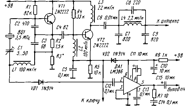
Encyclopedia of radio electronics and electrical engineering / Civil radio communications This direct conversion micro transceiver is designed for QRPP CW operation on the amateur bands 20-80 meters. In amateur radio magazines, in particular, in the American magazine "CQ", several of its variants were described, differing from each other in unimportant details (audio frequency amplifier circuit, switching circuits). The output power of the transceiver is up to 500 mW. The circuit diagram of the transceiver is shown in the figure. The cascade on the transistor VT1 is a master oscillator during transmission and a local oscillator during reception. The cascade on the transistor VT2 is the output stage during transmission and the mixing detector during reception. An audio frequency amplifier is assembled on the DA1 chip. The operating frequency of the local oscillator is stabilized by a BQ1 quartz resonator. Its fundamental resonance frequency must match the output frequency of the transmitter. It is impossible to use resonators operating on harmonics here. For a range of 80 meters, in particular, an inexpensive resonator at a frequency of 3,5685 MHz, used in imported color TVs and commercially available on Russian radio markets, is suitable. The local oscillator is assembled according to the "capacitive three-point" scheme and has a node for shifting the operating frequency during the transition from reception to transmission. It is necessary to ensure normal auditory reception of the correspondent's telegraph signals and should be about 800 Hz (the exact value is not critical). The shift of the operating frequency is provided by a series oscillatory circuit C1L1, the resonant frequency of which, at the middle position of the rotor of the tuning capacitor C1, must correspond to the frequency of the quartz resonator BQ1. The frequency shift circuit works like this. When the key is not pressed (receive mode, the cathode of the diode VD1 is not connected to the common wire), the operating frequency of the local oscillator is determined by both the quartz resonator and the oscillatory circuit L1C1. Depending on the position of the tuning capacitor rotor, it can be higher or lower than the frequency of the quartz resonator. When the key is pressed (transmission), coil L1 will be shunted by diode VD1. In this case, the operating frequency will be slightly higher than the frequency of the quartz resonator due to the effects of capacitor C1. For reliable shunting of the L1 coil, the VD1 diode opens when the voltage is transmitted, which drops across the resistor R3 (it is selected experimentally, it can be excluded). High-frequency voltage from the local oscillator is supplied to the base of the transistor VT2. When the key is pressed, the emitter of this transistor is connected to ground. In this case, the cascade on the transistor VT2 is a conventional amplifier operating in class C mode. The signal amplified by it through the P-loop (L4C7C9) enters the antenna. Capacitor C8 forms a parallel circuit with inductor L4, tuned to the second harmonic the operating frequency of the transmitter, and serves to reduce its spurious emissions. Since the output power of the transmitter does not exceed 500 mW, this capacitor can be omitted. And without it, the level of spurious emissions from the transmitter will be less than normal. When the key is not pressed, the transistor VT2 performs the functions of an active mixing detector. The signal from the antenna is fed into the collector circuit. The detected audio frequency signal is selected on the R5C5 chain and fed to the audio frequency amplifier. For elements whose ratings depend on the operating frequency, the data in the figure are given for a range of 80 meters. In the range of 40 meters, capacitors C7 and C9 should have a capacitance of 470 pF, and in the range of 20 meters - 270 pF. The inductance of the coil L4 should be in these cases 1,1 and 0,6 μH, respectively. Transistor VT1 can be any high-frequency low power (KT312, KT315, etc.). Transistor VT2 - KT606 with any letter index. There is no direct analogue for the LM386 microcircuit among domestic microcircuits. But almost any low-power UHF on a microcircuit is suitable here, for example, K174UN7 in standard inclusion or on an operational amplifier. Diodes VD1 and VD2 - any high-frequency silicon, for example, KD503 and the like. Literature
Publication: N. Bolshakov, rf.atnn.ru
The world's tallest astronomical observatory opened
04.05.2024 Controlling objects using air currents
04.05.2024 Purebred dogs get sick no more often than purebred dogs
03.05.2024
▪ Simplifying the processing of wood into biofuels ▪ About the benefits of building underground parking ▪ The new analogue of GPS will not need satellites
▪ site section And then an inventor (TRIZ) appeared. Article selection ▪ Article Sound in the car. The art of audio ▪ article What were the Middle Ages? Detailed answer ▪ article Odor Absorption by Porous Substances. Chemical experience
Home page | Library | Articles | Website map | Site Reviews www.diagram.com.ua |


 Arabic
 Bengali
 Chinese
 English
 French
 German
 Hebrew
 Hindi
Hindi Italian
 Japanese
 Korean
 Malay
Malay Polish
 Portuguese
 Spanish
 Turkish
 Ukrainian
 Vietnamese

 Leave your comment on this article: